This thread has been locked.

If you have a related question, please click the "Ask a related question" button in the top right corner. The newly created question will be automatically linked to this question.

ADS125H02: ADS125H02 RegisterWrite Problem

Part Number: ADS125H02
Other Parts Discussed in Thread: ADS131E08, ADS131M04, ADS1220

Hello,

I try to use the ads125h02 for a project and have some difficulties. I am able to read all internal registers, but can not write on them.

For example - Mode1 Register: I want to use the pulse conversion mode and a delay of 119µs

input:

data[0] = 0x43 (base 0x40 + 0x03 for mode1 register)
data[1] = 0x15
data[2] = 0xD8 (calculated CRC)
data[3] = 0x00

output:

data[0] = 0xFF
data[1] = 0x43
data[2] = 0x15
data[3] = 0xD9 (I except 0xD8..)

If I read the mode1 Register it shows only the default value and not the one that I set.

I already checked if the register is locked, when I read the status0 register i get 0x01, which seems to be correct to me. Where should i look for an error?

I use a Atmel SAMG55 as Master and SPI with DMA

  • Hi Kamal,

    Can you provide a logic analyzer shot of your incoming and outgoing communication (DIN and DOUT)? And have you checked these signals with an oscilloscope to ensure they are free of noise? A schematic of your system would also help.

    -Bryan

  • Hello Bryan,

    thank you for your quick reply.

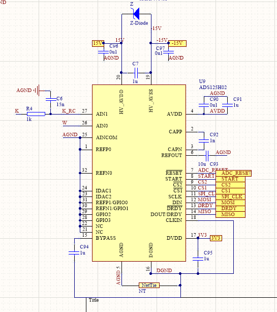
    I don't have any logic analyzer shots from DIN and DOUT. I work right now from home and can only go to the office next year. I checked all voltages and they were absolutely fine. I use a flash chip via SPI(3.3V) and a RTC with I2C which work fine. I have a 24V power bank which is used for 5V and 3.3V (LMZMZ23601), +- 15V (Traco TMR6) and analog 5V (ADR435). The netTie is just copper, I like to use it as a symbol for a better overview

    Here is the schematic of the ADC, where w is a 1-10V analog signal, and K_RC, a amplfied strain gauge signal

    is this any help for you ?

    I have my debugger at home, Reset is high and start is low. All ICs are on the same PCB (20x10cm) and I just use 1 Mhz SPI Speed, so the spi frequency shouldn't be a problem, which is why I did not use any terminating resistors on the SPI Line.

    the longest trace is spi_clock (20mm length, 0.2mm width with 2 vias), the other spi signals have a length between 10-20mm with up to 2 vias)

  • Hi Kamal,

    Can you read from/write to any registers correctly? You said you read back STATUS, but can you try to change any other register settings and see if those values can be read back?

    Since the CRC is giving you D9 instead of the expected D8, that would suggest there is a communication error. The corresponding command for a CRC value of D9 is 00 02, which is effectively a NOP command per Table 16.

    Since the ADS125H02 has 2x CS pins, are you sure you are selecting the correct CS pin to talk to the different registers? And could there be any other traffic on the SPI lines, or contention on the CS pins, that could interfere with the digital communication?

    I also see split ground planes in your system (or at least DGND and AGND nets), which could be an issue. Generally we recommend a solid ground plane to avoid ground noise.

    -Bryan

  • Hello Brian, thank you for your reply. I can read all registers correctly (always read the reset value), but can not write any.And yes I am sure to select the correct cs because I read mode4 register correctly when I use cs2 only. I have very noise sensitive analog Sensors, thats why i have  separate ground Plane as a Layer, which are connected in a star topology at the ADC. I Use this principle with several other Projects (ads131e08, ads131m04, ads1220 and more) and ist was always fine.

    I will try to get an oscilliscope to check the spi signal asap.

    Edit: For test purposes i changed all register values to non default

    mode0-In:       mode0-out: (correct crc,read after write shows correct value 0x4c)
    0x42               0xff
    0x4c               0x42
    0x45               0x4c
    0x00               0x45

    mode1-In:       mode1-out: (wrong crc, read after write shows correct value 0x15)
    0x43               0xff
    0x15               0x43
    0xd8               0x15
    0x00               0xd9

    mode2-In:       mode2-out: (correct crc, read after write shows correct value 0x40)
    0x44               0xff
    0x40               0x44
    0x1f                0x40
    0x00               0x1f

    mode3-In:       mode3-out: (wrong crc, read after write shows correct value 0x01)
    0x45               0xff
    0x01               0x45
    0xca               0x01
    0x00               0xcb

    ref-In:              ref-out: (correct crc, read after write shows reset value 0x05 instead 0x11)
    0x46               0xff
    0x11               0x46
    0x85               0x11
    0x00               0x85

    mode4-In:       mode4-out: (correct crc, read after write shows correct value 0x44)
    0x50               0xff
    0x44               0x50
    0x00               0x44
    0x00               0x00

    So I have several wrong CRCs, but most of the time the difference to the correct value is 1, and every readout with exception of ref register is correct. I am going to try different values for the ref register with the internal reference enabled and see if its gonna have an effect and yes I am sure that I have the ADS125H02 instead of 01 because I read out the correct device ID (0x62) and checked the order nr multiple times.

    Edit2: If I use 0x00 for ref as register value, I read out the correct value. Is it possible that there is a problem with the internal reference?

  • Hi Kamal,

    So, you are able to do the following after I read through your edits: read and write all registers (at least the ones you have tried thus far), though sometimes you are getting a CRC error? Is that accurate?

    Have you tried reading data yet? Or at least start the conversion process and monitor DRDY for pulses at ~1/data rate to check this functionality as well? You could also try reading known value such as the temp sensor or supply readback just to get a baseline for device operation.

    Thus far, everything you are describing sounds like digital communication issues, so I would start there once you have the oscilloscope and logic analyzer. You might also try adding in those termination resistors on the communication lines just in case there are issues on the clock signals, etc.

    -Bryan

  • Hello Bryan,

    I can write every register with some data(did not try every possible combination) except the register with special values. I don't get a "CRC Error", the DOUT just shows a different CRC value (+-1 of the value I calculated) but the registerdata is still written to the register in every case I tried with the exception of the ref register.

    I can read data, I tried the temperature sensor and hvdd/36 as input which seem to be realistic and reproduceable but I would like to use the internal refernce, not the AVDD for better SNR.

    I will try to use the logic analyzer as soon as possible. If you have more ideas where i can look for an error, please let me know.

  • Hi Kamal,

    So the stored data you are reading back from your MCU is showing a bit flip in the CRC data in some cases (compared to what you calculated), however the register settings are taking effect? If that is the case, then something is causing readback issues on the digital communication lines. Otherwise, if the CRC values didn't match, the ADC would not recognize the register settings and they would remain as the defaults. So the ADC appears to be receiving the correct data, changing the configuration settings, and outputting data correctly on DOUT, but somewhere in the transfer from ADC to MCU there is an issue.

    This will definitely require a logic analyzer and a scope to troubleshoot. Let me know what you find after you procure these instruments.

    -Bryan