This thread has been locked.

If you have a related question, please click the "Ask a related question" button in the top right corner. The newly created question will be automatically linked to this question.

ADS114S08: how to use AIN6 & AIN7 OF ADS114S08

Part Number: ADS114S08
Other Parts Discussed in Thread: ADS114S06,

How to use AIN6 & AIN7. 

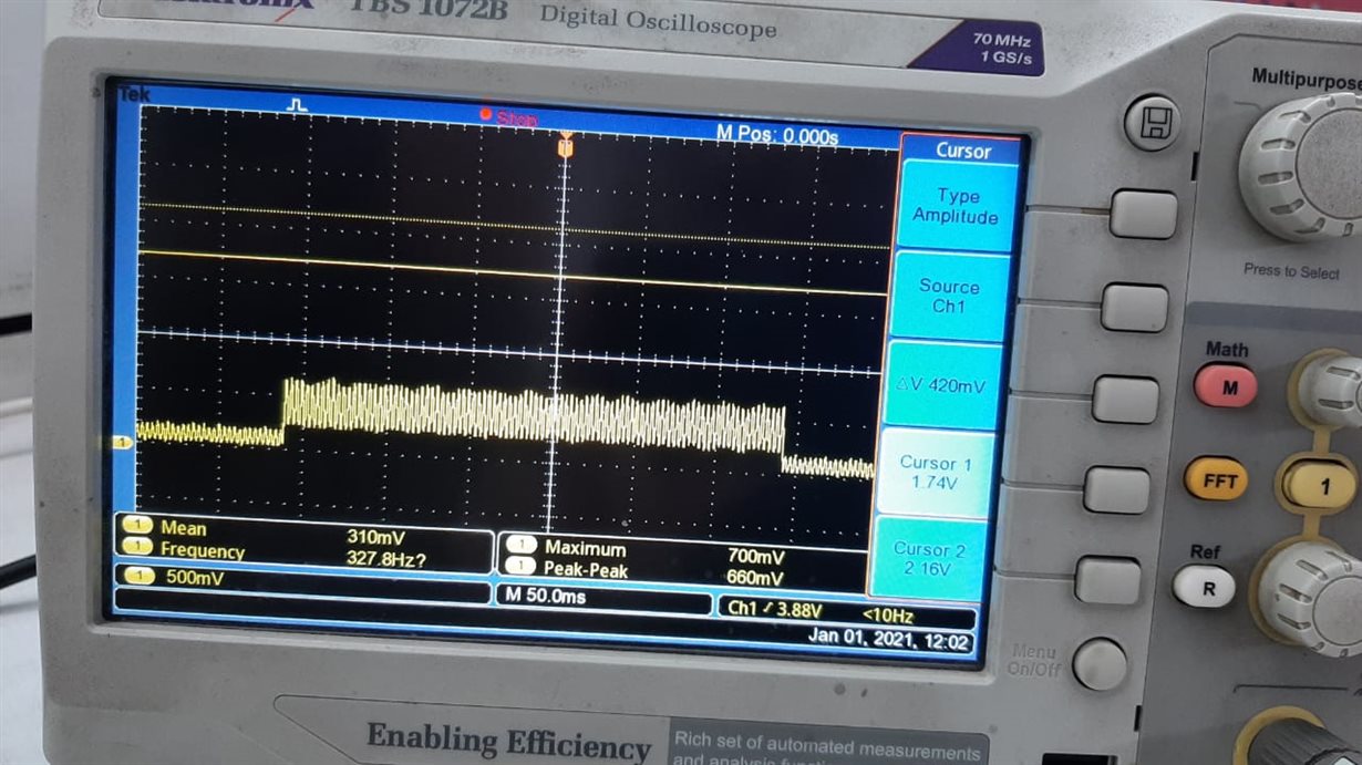
I have initialized the IC as follows  & trying to read channel data with respect to AINCOM but it is not providing the correct data & a kind of wave form is available at channel 7.

regWrite(0x01,0x80);
regWrite(0x02,0x5C);
//regWrite(0x03,0x00);
regWrite(0x03,0x08);
regWrite(0x04,0x02)
regWrite(0x05,0x3A);
regWrite(0x06,0x00);
regWrite(0x07,0xFF);
//regWrite(0x08,0x00);
regWrite(0x08,0x40);
regWrite(0x09,0x10);
regWrite(0x0A,0x00);
regWrite(0x0B,0x00);
regWrite(0x0C,0x00);
regWrite(0x0D,0x00);
regWrite(0x0E,0x00);
regWrite(0x0F,0x40);
regWrite(0x10,0x00);
regWrite(0x11,0x00);

  • Hi Dileep,

    Thank you for your question. Many of our engineers are taking vacation due to the Christmas holiday in the US. Once they return from the holiday, they will address your question. I apologize for any inconvenience this causes. 

  • Hi Dileep,

    According to the register settings you have provided:

    • Measuring between AIN5 and AINCOM
    • PGA enabled, gain = 1
    • Int oscillator, sinc3 filter, DR = 10 SPS
    • No VREF monitors, both VREF buffers disabled, int VREF is always on
    • IDACs off
    • VBIAS = AINCOM (so AINCOM is at (AVDD+AVDD)/2)

    Are these the settings you wanted? It seems like you wanted to measure at AIN6 and AIN7, but these are not selected per the register settings you have provided.

    If you are having communication issues:

    • Can you write to a register and read that register back to make sure the intended settings have been applied?
    • Can you start the conversion process and poll DRDY to see if you get DRDY pulses at ~1/data rate?
    • If you still have issues, can you provide oscilloscope and/or logic analyzer captures of the SPI transactions so we can see what is going on?

    Let me know.

    -Bryan

  • Given commands are used only during initialization. After that i am able to read channel data from AIN0- AIN5 changing channels {regWrite(0x02,0x0C); -  regWrite(0x02,0x5C); }one bye one. But at the AIN6 & AIN7 pins a kind of waveform is present. 

    Am i doing right steps to raed data from AIN6 & AIN7 or are these pins still in another mode ????

  • Hi Dileep,

    This might seem like a silly question, but I want to make sure before we continue: can you confirm that you are using the ADS114S08 and not the ADS114S06? The AIN6 and AIN7 channels on the ADS114S06 are not available, so it would make sense that they would not behave the same as AIN0 through AIN5. If you cannot read the topside marking on the device, you can read back the device ID register to be sure.

    Let me know.

    -Bryan

  • Yes it is ADS114S08. And i know it has AIN6 & AIN7.

  • Hi Dileep,

    Can you then explain what happens when you switch to AIN6 and AIN7? You said "a kind of waveform is present", but it is not clear what this waveform is and what you were expecting to see.

    Can you also provide a schematic of your system so I can see how your inputs are connected?

    Finally, you can initialize all of your registers, then read them all back and share an image of the ADC's output for me to review? Thanks!

    -Bryan

  • I have connected AIN7 TO ground but still i am receiving around 5000 counts. Waveform image is attached for your reference.

  • Thanks Dileep,

    Can you also send your schematic and register setting read back, as requested? And please let me know where on the schematic your oscilloscope is connected to? Is that at DOUT, or is that at AIN7?

    -Bryan