Because of the Thanksgiving holiday in the U.S., TI E2E™ design support forum responses may be delayed from November 25 through December 2. Thank you for your patience.

This thread has been locked.

If you have a related question, please click the "Ask a related question" button in the top right corner. The newly created question will be automatically linked to this question.

ADS1299:About the noise problem of ADS1299

Part Number: ADS1299
Other Parts Discussed in Thread: SN74AHC1G126, LMK1C1104

Hello, Ryan! I'd like to ask you some questions.

we encountered the following problems in the process of debugging ADS1299: Connect four ads1299 chips in daisy-chain mode to receive data and connect REF, GND and all inputs in parallel through 10K resistors at the input end. When testing the noise, spike interference with a frequency of about 9.76HZ will occur, but on a single ADS1299, or all four ADS1299 front ends are short-circuited, there is no such noise. Is it the internal noise of the ADS1299 or is it possible that other places will interfere with it?


Here's our circuit:

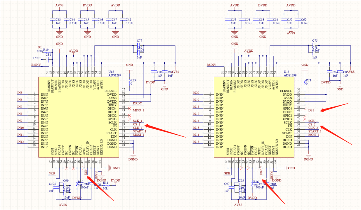
First of all, this is a partial schematic diagram of the four ADS1299:

As we can see, we used DAISY_IN, DOUT, CS1, and CS2 pins at the same time because we want to use both daisy-chain mode and cascade mode at the same time. Use multi-cascade mode (cascade mode) to configure each ADS1299 individually, and then use daisy-chain mode to read ADC conversion data with four ADS1299s together.


At the same time, in order to ensure that the four ADS1299s have the same clock source, a 2.048Mhz active crystal oscillator (oscillator) is used, and then input to each ADS1299 through a 1:4LVCMOS Clock Buffer, namely LMK1C1104. At the same time, in order to prevent the second ADS1299 and the third ADS1299 from being too far away from the daisy-chain mode (daisy-chain mode) reading data error, I also added a piece of data between the second DAISY_IN and the third DOUT Buffer (single bus buffer), namely SN74AHC1G126, is as follows:

The next phenomenon is:

Our first choice is to short-circuit all the inputs of the four ADS1299s, as well as SRB and BIADOUT. The noise is very low and there is no obvious interference. No obvious noise appears on the time domain graph and frequency domain graphh.

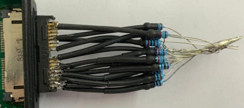
But when we connect all inputs, SRB and BIADOUT in parallel through resistors, as follows:

In this case, there will be a spike with a frequency of about 9.76hz, which is very obvious on both the time domain graph and the frequency domain graph.

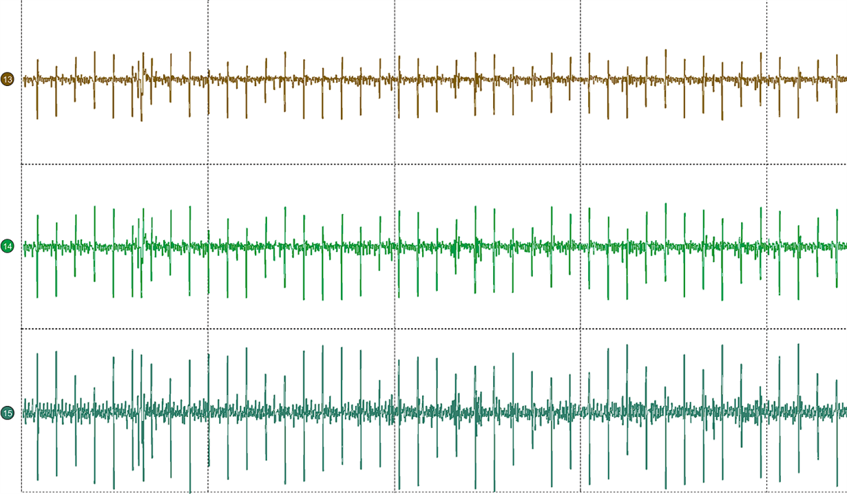
We try to connect at least two resistors to the input of each ADS1299. Just look at the input signal connected to the resistor. We can see the spikes as follows:

One of grids is the window length of 1s, and there are about 10 peaks in one lattice.


Here is the frequency domain of the two minute data:

As shown above, we can see that there is a frequency of 9.76HZ and its frequency doubling.


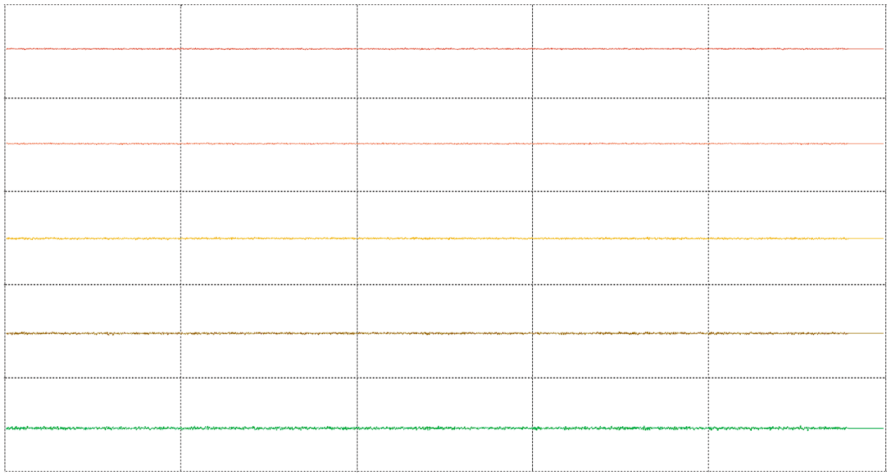
There is no noise when the input is short-circuited, and there is noise when the electron is connected. At first, we suspected that it was caused by resistance, so we used a circuit board with only one ADS1299. As before, we measured the input terminal in parallel with the resistance and found that there was no noise. Low, the signal is as shown:

As shown above, it can be seen that there is no spike noise when there is only a piece of ADS1299.


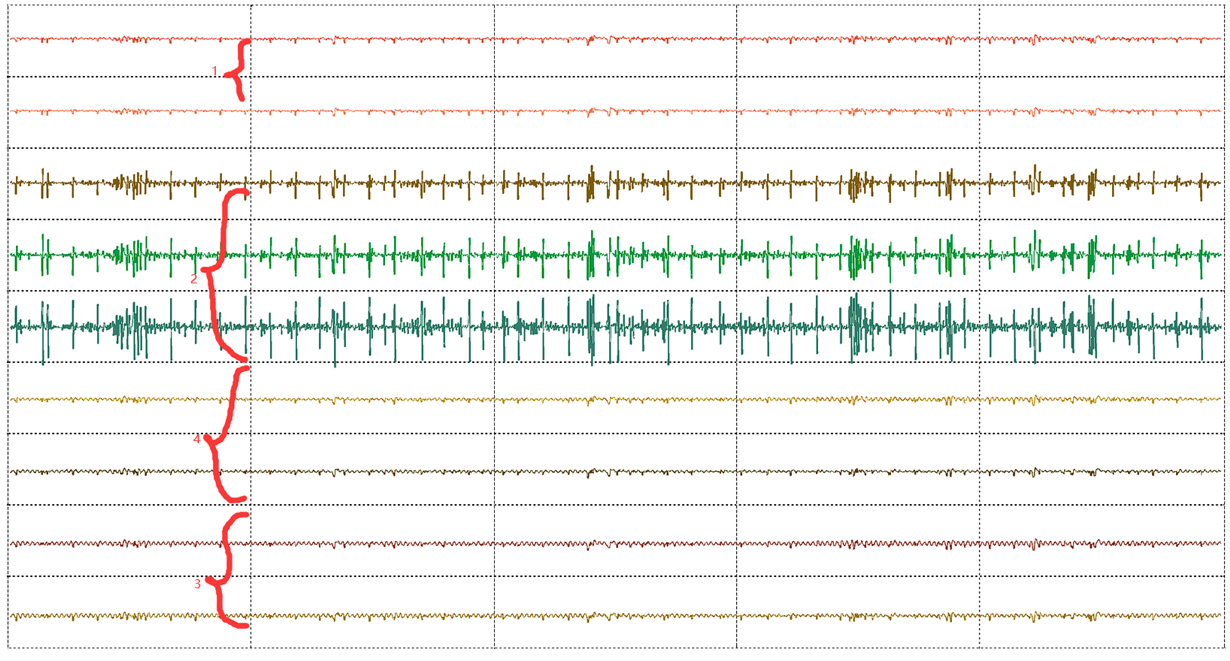
And we also found a strange thing, each of our ADS1299 has at least two inputs connected to resistors, the test found that only the second signal noise is abnormally high, the noise of the other pieces is basically the same, and we have several After the circuit board was changed, it was found that the second piece was very noisy. Explain that it may be a design problem or ADS1299's own problem, it should not be external influences such as welding. As shown:

Because a signal buffer (single bus buffer) is added between the second and third slices, it is suspected to have an impact on the signal, but after shorting the two slices DAISY_IN and the third slice DOUT, it is found that there is no signal improve.

It should be noted that the power supply circuit and main control of the four-chip ADS1299 and the single-chip ADS1299 are exactly the same. At the same time, we also analyzed the source of this 9.76hz, 2.048Mhz oscillator is divided down to 7.8HZ, SPI communication rate is 5Mhz down to 9.53HZ, and the main control 80Mhz is divided down to 9.53HZ. All power supplies use LDO without oscillation frequency. Is it caused by RC oscillation? Finally, the source of the frequency was not found.


We now mainly have the following questions:

1. Will ADS1299 generate a frequency of 9.76HZ? If not, where is this most likely introduced from?

2. The noise of the second ADS1299 is very high. What causes this phenomenon? Is there any way to eliminate it.

3. There is no noise while short-circuited and there is noise when the resistance is connected?

4. For the same circuit, why is there no noise with a piece of ADS1299 and why is there noise with four pieces of ADS1299?


Ryan and the experts please help me to answer, I know there are a lot of descriptions, but this has troubled us for a long time.

Best regards

  • this is a partial schematic diagram of the four ADS1299:

    • @Alexander Smith,@Ryan Andrews,@TCT,Please help to reply to this question,thank you very much.

  • Hi,

    Thanks for the post. Please see my comments inline below. 

    1. Will ADS1299 generate a frequency of 9.76HZ? If not, where is this most likely introduced from?

    >> There is no internal generated frequency of 9.76Hz for the ADS1299. The AC lead-off frequency is operating at either 7.8Hz, 31.2Hz or fDR/4. This specific 9.76Hz is probably couple externally to the device. It is possible to have EMI interference such as external light source, monitor, and other nearby noise source.

    2. The noise of the second ADS1299 is very high. What causes this phenomenon? Is there any way to eliminate it.

    >> See comment 4. 

    3. There is no noise while short-circuited and there is noise when the resistance is connected?

    >> When you short the input, any external noise coupling will appear as common-mode signal which will be rejected by the ADC and hence you don't see significant noise with the input shorted.  

    4. For the same circuit, why is there no noise with a piece of ADS1299 and why is there noise with four pieces of ADS1299?

    >> Is the 4 ADS1299 populated in the same EVM hardware? There may be some layout or some other factors that may cause the discrepancy.   

    Can you elaborate on the 9.53Hz signal mentioned in the description regarding the SPI communication and main control?

    Thanks.

    -TC

  • Hi, TC,

    Thank you very much for your reply!

    Regarding comment 3, my input is short-circuited, and there are certain similarities in parallel with the resistor, because on the PCB, the input terminal of ADS1299 will be connected in series with a certain resistance resistor, which acts as an RC low-pass filter, so it is in the shell After all the input terminals of the ADS1299 chip are short-circuited, it is equivalent to all the input pins of the ADS1299 chip and SRB, BIAS are connected in parallel through a resistor, but the resistance is relatively small, but there is almost no noise at this time. But when I connect some external resistors, as seen in the question, the noise will become very loud at this time. What puzzles me is that the two methods are to connect the input pins of the ADS1299 chip in parallel through resistors, but the direct short circuit(The input ports in the PCB will also be connected in parallel through small resistance (within 10K)) of the input terminal has much lower noise than the parallel connection of the input terminal through external resistors. It only increases the resistance, why does this phenomenon appear?

    Regarding comment 4, we have used four ADS1299s on a piece PCB, and the layout is basically the same. 9.53HZ is not noise interference, it means that the SPI clock is 5M, 5M/(2^19)=9.53HZ, which is different from 9.76hz, so the SPI clock interference is excluded.

  • Hi,

    Is there any RF circuitry on the board along with the ADS1299? There may be some EMI interference that you see when the external resistors is connected to the inputs. If possible, please turn off or disable any RF circuitry and see if this helps with the tone you see in your FFT spectrum. The other experiments will be to use the EMI shield for the ADS1299 and check if this helps eliminate the tone.

    Thanks.

    -TC

  • Hi,TC

    We do have some radio frequency circuits, but they cannot be shut down for the time being. Now we suspect that the large current of the radio frequency circuit has caused the impact on the ground and the power supply. Is this possible?

    Thanks.

  • Hi,

    It is possible the coupling is injected through the power supply and ground. The high PSRR of the device will help to alleviate the coupling from the power supply. However, the noise injection will be more significant if the ADS1299 device is sharing the same ground as the RF circuitry. It will be helpful to debug the issue if we can isolate the RF circuitry from the sensitive input circuitry of the ADS1299.    

    Thanks.

    -TC

  • Hi,

    Okay, TC thank you very much , but we are using a battery with only one ground. Is there any good way to separate the ground?

    Thanks.

  • Hi,

    We have some layout recommendations and guidelines in Section 12 of the datasheet for your reference. I would suggest you refer to some of the manufacturer's RF layout recommendations to minimize any interference issues.

    Thanks.

    -TC

  • Hi,

    We have reference this design.

    TC thank you very much ,