This thread has been locked.

If you have a related question, please click the "Ask a related question" button in the top right corner. The newly created question will be automatically linked to this question.

ADS1018EVM: ADS1018EVM Questions

Part Number: ADS1018EVM
Other Parts Discussed in Thread: ADS1118EVM, ADS1118, ADS1018

All:

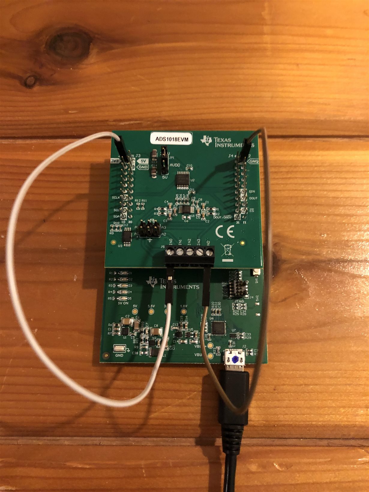
I have set up ADS1018EVM - had to update drivers manually via Device Manager using PAMB_USB_Driver_Install...

When I run "software GUI" from Eval Board instructions, I do get Hardware Connect. However, even though my board says ADS1018EVM, tool shows ADS1118EVM.

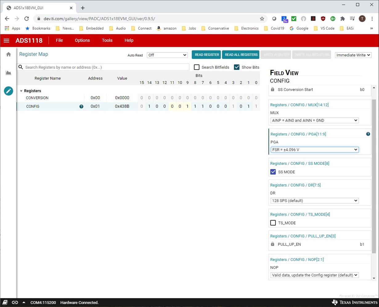
I clicked on Register Map to get at the registers, clicked on CONFIG and filled out for AIN0 and gnd (single-ended A0), PGA for +-4.096, SS Mode, Valid Data update (NOP).

How do I send the command and receive Conversion? I physically have set GND to ground and AIN0 to 3.3 volts via jumpers. So I should see non-zero value in Conversion.

However, I am not sure how to send command(s) to see results.

Help!

Regards,

Todd Anderson

  • I do have a MSP-EXP432P401R LaunchPad, and the ADS1018EVM looks pin-compatible to the LaunchPad!

    Do you have c-code that will run on the LaunchPad to enable evaluation of the ADS1018EVM?

    (I can modify some example code, but it would save a lot of time if some code already existed.)

    Regards,

    Todd Anderson

  • Hi Todd,

    Let me answer your last post first.  We are working on releasing example code but unfortunately it will not be available for about 4-6 weeks.  

    The GUI for the ADS1018 and ADS1118 is the same as is the firmware.  There is an EEPROM programmed on the board used to identify the device on the board.  The ADS1018 powers up in a low-power state and in single-shot mode. To initiate a conversion in the GUI you need to go to the Chart tab and actually Collect some data.  When in single-shot mode a conversion would normally be initiated in firmware by setting bit 15 to '1' and writing the register.  To simplify the firmware to GUI synchronization, this operation is ignored in the firmware and the firmware keeps track of whether the device is in single-shot mode or continuous conversion mode.  If you choose continuous conversion mode, then once conversion data has been collected in the Chart tab, you could go back to the Register tab and read the register for conversion data and it should update with the latest conversion result.

    In addition there is a discussion in the user's guide but it may not be clear, but there is actually only one register in the ADS1018.  The firmware/GUI was developed in such a way as to create a pseudo register for the conversion data for viewing.  The firmware always communicates to the ADS1018 in 32-bit communication mode where the conversion data are read as well as the configuration register settings.  The easiest way to display the conversion data and configuration data is to show the entire 32-bit communication as two separate registers.  So the use case for the GUI/firmware is not the same as would actually used in an application.

    Best regards,

    Bob B

  • Thanks for your reply. I did set up the config register for =-4.096
    If I use 3.3v as input to A0 (single-ended), I should get 3.3/4.096 x 16384 (for 16 bits) = 13200 counts.
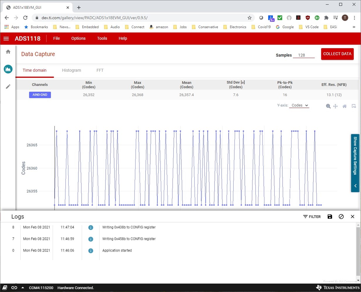
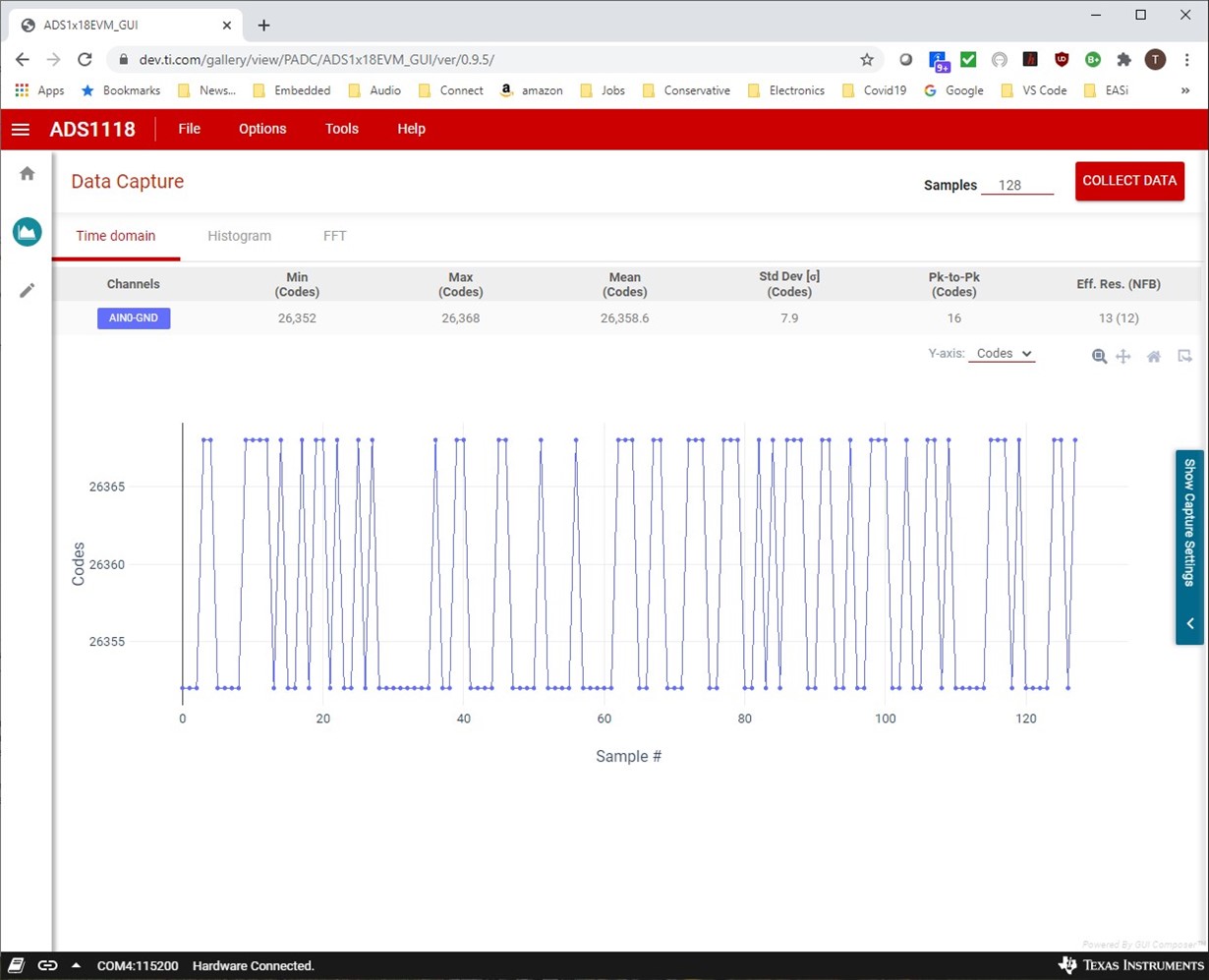
    However, I am seeing roughly double in the data capture window. (26,368 max) This is a bit confusing, but at least it could be accounted for as a bit-shift.
    It does look like the application is treating my ADS1018EVM as ADS1118EVM. Anything more you can tell me? 
    I do plan to connect the ADS1018EVM to a different device, so this at least gets me started.
  • Hi Todd,

    It looks like you tried to include a picture.  Unfortunately you have to insert any pictures as a file using the computer icon or attach the file with the paperclip icon.  If you could attach a screen shot of the tools information from the GUI that would be helpful.  Also, screenshot the register page for me after collection of the data.

    Best regards,

    Bob B

  • Hi Todd,

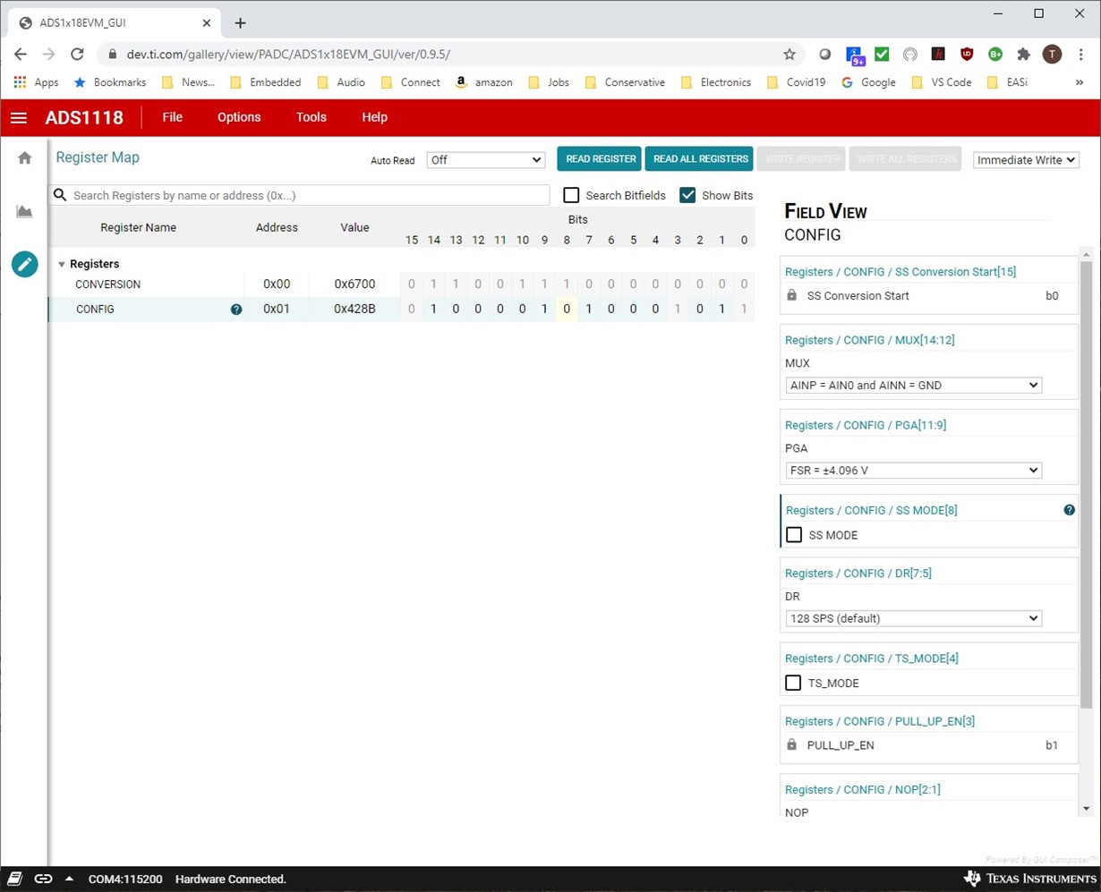
    Sorry for all of the confusion.  As I said the firmware/GUI is the same for both the 12-bit and 16-bit devices.  It does appear that the GUI is incorrectly showing the device on the EVM.  To make sure that we are not missing any important information regarding this issue we want to make sure that something is not messed up with respect to the programming of the device.  Can you switch the device to continuous conversion mode and collect some data then go to the register page and Read All Registers.  I should have given this detail previously.  If you send me that screen shot it would be helpful.

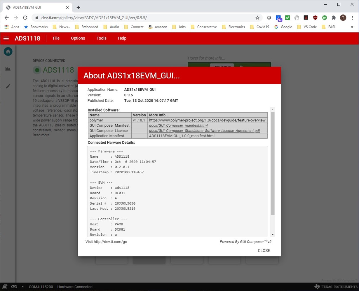
    Also, it would be helpful for me to see the information from the Help drop down and the About information.  So send that info as a screen shot and once I have that information I think we can get things back on track.

    Best regards,

    Bob B

  • Hi Todd,

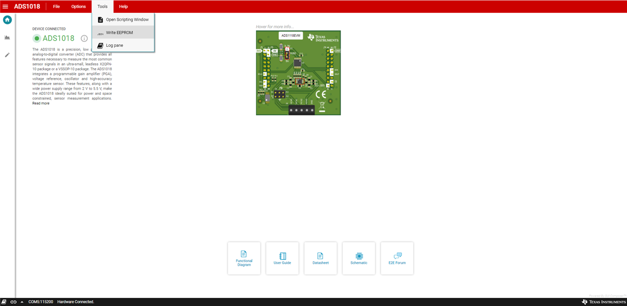
    Thanks for the info.  I see that you are not using the latest version of the GUI which should be 1.0.0.  To get the GUI to correctly identify the ADS1018EVM, got to the GUI home page and with the EVM connected press the keys at the same time 'Ctrl-Alt D' which will place the GUI into a special mode.  From the Tools drop-down menu you should see the following:

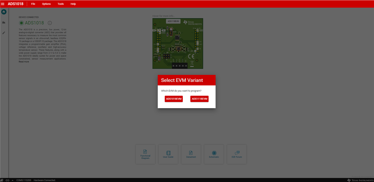
    Select Write EEPROM and a pop-up box should appear as follows:

    Select the ADS1018EVM variant.  You should see at the bottom left that the EEPROM write was successful.  Restart the GUI and you should now have the EVM recognized as the ADS1018EVM.

    Best regards,

    Bob B

  • Bob:

    Thanks, and I do have a fault in my original equation.

    Because I am using single-ended, the max count is 4096/2 = 2048.

    I am now getting 1647 counts

    And 1647/2048 * 4.096 = 3.294 volts, ~3.3 volts!

    Regards,

    Todd Anderson