This thread has been locked.

If you have a related question, please click the "Ask a related question" button in the top right corner. The newly created question will be automatically linked to this question.

TLC7528: Multiplying DAC Settling Time to Frequency Limit

Part Number: TLC7528
Other Parts Discussed in Thread: DAC8811

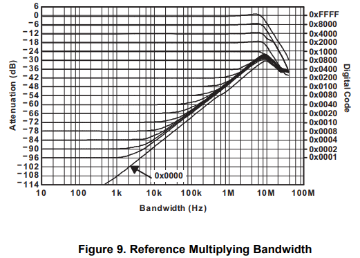
In a circuit such as Figure 9. of the TLC7528 datasheet,  excluding effects of the circuit external to the DAC, for DAC selection, how can figure out the frequency limitations of a circuit like mentioned above?  Presumably, the settling time of the DAC is proportional to the frequency limit of using the DAC as an attenuator or even as a digitally controlled resistor of sorts, but how can I figure this out?  I am interested in incorporating the tlc7528 or another multiplying DAC into a function generator I am designing as a digitally controlled attenuator and other similar circuits, but I am unsure of how directly the settling time applies to the frequency limits on it.  

Thank you!

  • Hi Fred,

    An MDAC can be thought of as a resistor divider, at code 0x00, you have the least impedance.  At code 0xFF, you have the most. There are parasitic capacitors created by the device, the package, and the PCB.  That cap and the resistance create a RC filter, which dominates your BW.  

    We do not have a plot for the TLC7528, but consider the DAC8811.

    This is basically the same behavior you would see with the TLV, but you would probably need to characterize the parasitic capacitance.

    Thanks,

    Paul