This thread has been locked.

If you have a related question, please click the "Ask a related question" button in the top right corner. The newly created question will be automatically linked to this question.

ADC3444: proper matching to input of ADC344x with anti-alias filter from source impedance of 6.6 k in parallel with 3.6 pF??

Part Number: ADC3444
Other Parts Discussed in Thread: THS4541, , ADC3643EVM,

I am working on an application where I must use an ADC344x series device hooked to a device with an output impedance of 6.6 K ohm in parallel with 3.6 pF. I understand that the input impedance of the ADC344x device is 9K ohm differential. I want to use a differential circuit. But, rather than just interface, I need to include a low pass filter for anti-aliasing. I am hoping I can do this passively, but I suspect I will at least need one amplifier to convert the 6.6 K in parallel with 3.6 pf to a lower impedance. Is this correct? What would a good circuit look like to interface and convert impdeance levels between these two devices? Also, because we are dealing with a relatively low cutoff frequency, I am hoping to keep the impedance value for the LPF to 200 ohms or even less, but I don't know if this is possible.

  • Hi Ed,

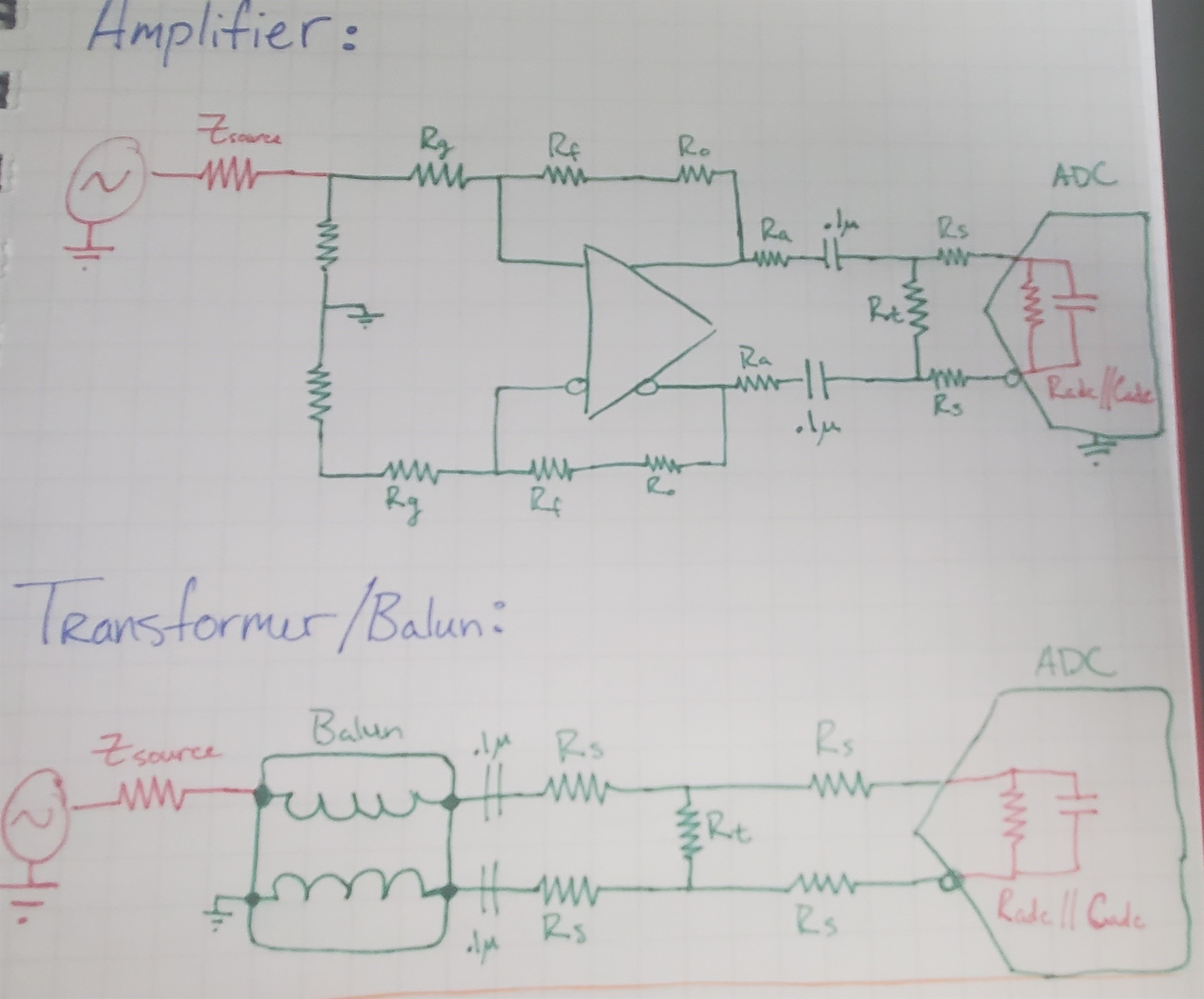
    For your differential circuit, you have a few options. You can take a transformer approach or utilize a fully differential amplifier, such as the THS4541. Our EVM designs typically filter on the balanced output of either the transformer or amplifier. Shown below is a basic approach of the differential circuit using both methods.

    I suggest to look at the schematics for the ADC3444EVM (found under "Design files") to see these circuits as they are implemented on the EVM and determine which best fits your application.

    Regards, Chase

  • Hi Ed,

    I've just realized the ADC3444EVM does not implement a fully differential amp approach. Below is a screenshot of the ADC3643EVM schematic showing this approach as well as filtering.

    Regards, Chase 

  • I guess my question is, whether I am using transformers or a differential amp, what impedance level should I design the filter for? What is the proper input impedance for this device? I see that most ADCs use 200 ohms differential, but I know there are differences. And, the data sheet says that the input impedance is 6.6 K in parallel with 3.7 pf. I gather I should resonate out the 3.7 pf with an inductor, but 6.6 k is very high and I don't see any way that any of the referenced circuits transform, say, 50 ohms to 6.6 K. Also, FWIW, the downconverter that I am using has an output impedance of 9K. Do I need to translate from 9k to 6.6k? (I am using the ADF5904). I am hoping that I can design the anti-alias filter with an impedance level somewhere between 50 and 200 ohms.

  • Hi Ed,

    Section 10.1 of the datasheet shows the differential input resistance vs input frequency for this ADC.

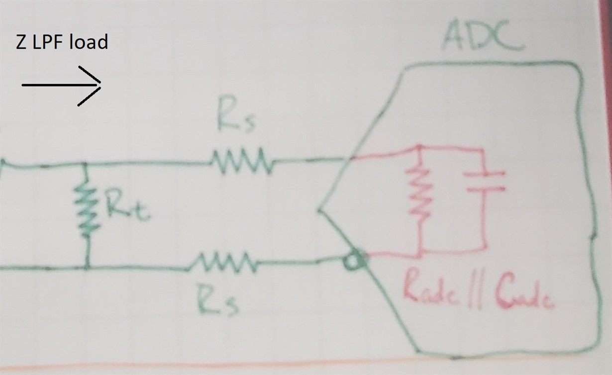
    Your LPF's load impedance should target Z_LPF_load =  Rt || (Radc + 2Rs).

    Regards, Chase

  • Hi Ed,

    Couple of items that might help. First, so we can understand this correctly.

    Can you please provide a rough block diagram of the setup and anti-aliasing filter?

    Second, when designing the filter and understanding the input impedance to the ADC, it is best to select the impedance in the middle of the band that is planned to use for the application.

    Hope this helps.

    Regards,

    Rob

  • I am trying to connect and filter the output of a ADF5904 downconverter to the input of the ADC344X. The center frequency is about 2 MHz, so the input impedance of the ADC344x should be about 6.6k || 3.8 pF. The output impedance of the downconverter is 900 ohms differential. I'm trying to determine the proper input and output impedances for the LPF, which needs to cut-off at about 4 MHz. Looking at figure 197 in your data sheet, it looks like your design is meant for a 200 ohm input impedance, but I am not sure. Also, you have 2 1:1 transformers. If your circuit is designed for 200 ohms differential impedance, is the impedance of the input generator also 200 ohms? I'm not clear on the input and output levels. Also, since the output impedance of the downconverter is 900 ohms differential, I assume that means my filter/match network must go from 900 ohms to the desired input impedance of the ADC344x, which I guess is supposed to be 200 ohms? I would prefer impedance levels as low as possible so as to make the passive filter values realistic.

    What would be the best architecture to interface and match these two circuits? I tried to attach a pdf of the block diagram, but I'm not sure if it made it.

    6278.block.pdf

  • Hi Ed,

    If your circuit is designed for 200 ohms differential impedance, is the impedance of the input generator also 200 ohms? 

    No. The signal generator has a source impedance of 50 therefore the load the signal generator sees is close to 50 for the entire network.


    Since the output impedance of the downconverter is 900 ohms differential, I assume that means my filter/match network must go from 900 ohms to the desired input impedance of the ADC344x, which I guess is supposed to be 200 ohms?

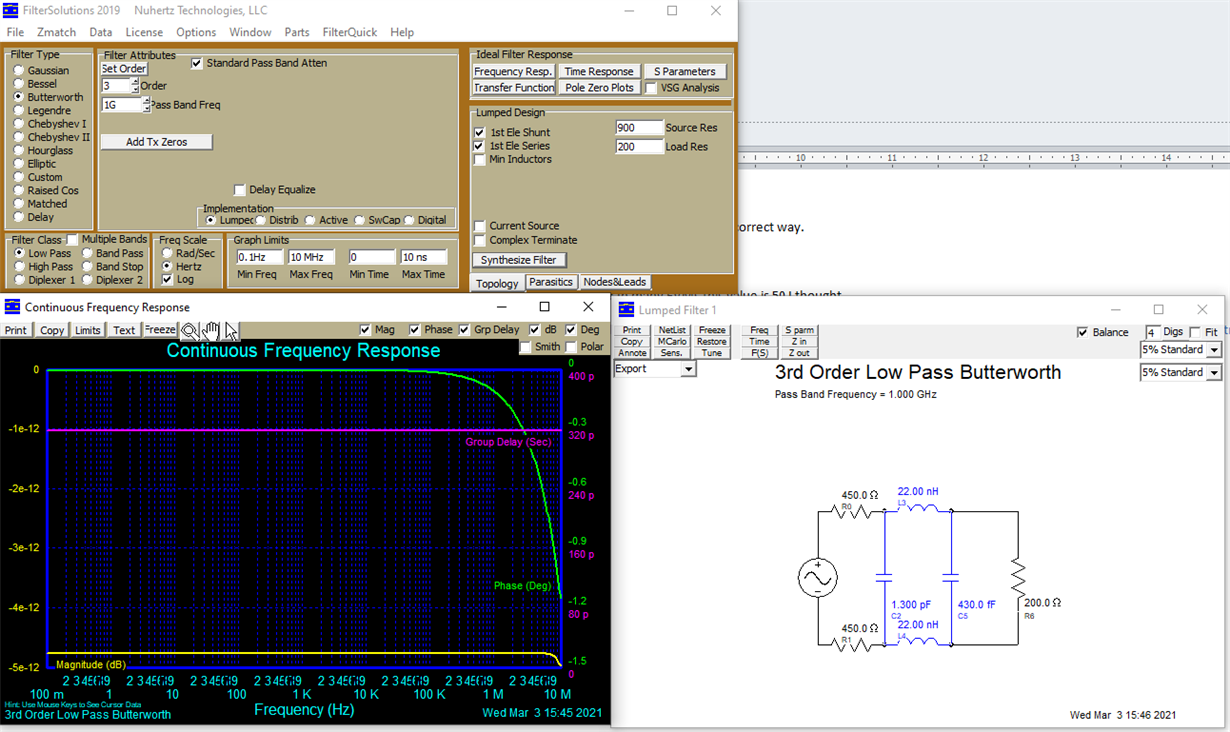
    Yes, 200 ohm is typical. The filter below should work for you having source and load resistance of 900 and 200 respectively. 

    Be aware that the output of your ADF5904 is 4Vpp and the input to the ADC3444 is 2Vpp so some attenuation is required. Please let us know if you have any additional questions. 

    Regards, Chase

  • OK, I think I am understanding this more. Actually, the fact that the driver has 4 vp-p with a 900 ohm source resistance (differential) may help. I obviously need to get that impedance lower--ideally to 200 ohms, or maybe even100 ohms differential. I guess I have two choices; either an op-amp to convert impedance from 900 ohms to something lower, or a transformer, or some combination. Even a resistor divider might be useful, although only as a part of the circuit.

    Now, some questions to make sure I understand the data sheet circuits, specifically figure 197. If I look at the circuit to the right of the second transformer and ignore the dc blocking capacitors, it looks like the ADC has an impedance of about 133 ohms differential. Is that correct? If you look at the circuit to the right of the VCM connection, it looks like the ADC input impedance is about 100 ohms differential, correct? Overall, it looks like that circuit is designed to go from a 50 ohm signal source all of the way on the left. Correct?

    Now, I would assume that I could install the filter between the two transformers with a 133 ohm differential impedance, or between to 2 25 ohm resistors and the 2 50 ohm resistors and the 22 pF capacitor with an impedance of about 100 ohms. Am I correct?

    I suspect that using a 4:1 transformer on the output of the downconverter along with, perhaps, some series resistors to then have a filter in the 100 to 200 ohm impedance range.

  • Hi Ed,

    Your understanding is correct. If you have any additional questions, feel free to let us know!

    Regards, Chase