This thread has been locked.

If you have a related question, please click the "Ask a related question" button in the top right corner. The newly created question will be automatically linked to this question.

ADS114S08: Sending RREG command from a PIC32 controller

Part Number: ADS114S08

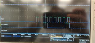
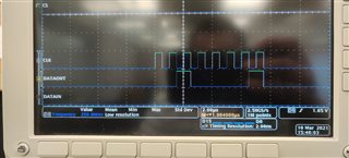
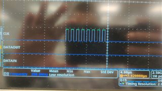
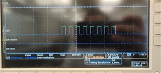
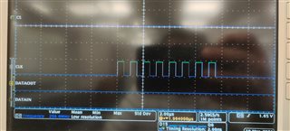
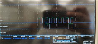
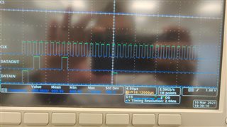
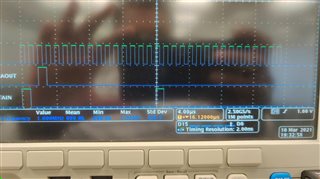
I have a PIC32 connected to the ADS114S08 and I'm trying to send a RREG command and read it but all I get is garbage. I have followed ever step in setting the SPI up and checked if the CS pin is low.. everything else looks fine.. but just not being able to work the ADC or get it to respond.

Do you have any code for initializing the SPI of PIC32 and sending one basic command that works?

  • Hi 6562906,

    Unfortunately we do not have example code for a competitor's device, but I would be glad to help you troubleshoot your communication.  Make sure that the supplies for AVDD, DVDD and IOVDD are all at nominal operating voltage.  For example, the device will not communicate if AVDD is missing.  Also make sure that the RESET pin is set high.

    It would be helpful to see oscilloscope or logic analyzer shots of the communication to verify that the command is being transmitted correctly.

    Best regards,

    Bob B

  • Hi Bob,

    I have connected the AVDD, DVDD and IOVDD to a 3.3v supply and pulled the RESET pin high. I will send you screenshots soon

    Thanks,
    Rohan

  • Hi Bob,

    I have sent 0x21 and 0x0 to the ADC. and I have recorded it. Please take a look and ler me know what you think I might be missing.. I'm not getting any response from the ADC

  • Hi Rohan,

    I think the biggest issue is you are clocking out the data on the wrong phase of the SCLK.  Data should change on the rising edge of SCLK and hold steady on the falling edge.

    The second thing is it would appear that you are not sending enough clocks.  The RREG command is two bytes followed by a NOP to retrieve the data.  So the sequence would be 0x21 (read register command starting at register 1), 0x00 (read 1 register), 0x00 (NOP is transmitted to collect the data).  Also throughout the entire communication the CS must stay low.

    Best regards,

    Bob B

  • Hi Bob,
    I did what you asked me to do in your last post but I'm still not getting the expected Rx data. Below are some shots of the comm.

    I made CS permanently low

    First I sent 0x21 followed by 0x00 and 0x00.

    Then I sent 0x20 followed by 0x00 and 0x00.

  • Hi Rohan,

    In each case you are clocking out the data that is in the output buffer.  It is showing as negative full-scale (0x8000) and because the data is in a ring buffer the data is repeated every 16 SCLKs because the command is not being decoded.  So the good news is the device is responding.

    However, there appears to be no data into the ADS114S08.  Verify that the data shown on the scope shot is also occurring on the DIN pin of the ADS114S08.  Check for a short between the DIN and CS pins where DIN might be held low along with CS.

    Best regards,

    Bob B

  • Hi Bob,

    I did not quite understand what you meant by the first half of your post above

    "In each case you are clocking out the data that is in the output buffer.  It is showing as negative full-scale (0x8000) and because the data is in a ring buffer the data is repeated every 16 SCLKs because the command is not being decoded.  So the good news is the device is responding."

    I have double checked the connections and they are fine. the data you see on the scope is extracted through taps on the ADC chip itself.

  • Hi Rohan,

    If a conversion takes place and finishes, the conversion result is automatically placed into the output buffer and will stay there until either a new conversion completes or a command updates the buffer with some other data.

    Can you send me your schematic? Which device package are you using?

    And when you 'double checked the connections' did you actually probe the pin on the ADS114S08 as opposed to vias or testpoints?  For example, if you have the suggested in line series resistance with the digital signals perhaps the resistor is open or a bad solder joint.  

    Best regards,

    Bob B

  • Hi Bob,

    Yes, I did probe the pins on the ADS114S08 and checked for the connectivity. I'm sharing the Schematic with you. I'm using a PIC32 from Microchip.PIC32 Schematic.pdf

    2620.ADC Schematic.pdf

    Please let me know what you think.

  • Hi Rohan,

    Thanks for the additional information.  Nothing in the schematic stands out to me as an issue.  I see that there are 2 ADCs and you are using 2 SPI peripherals. 

    • Are you able to communicate with other devices on the bus? 
    • Have you tried to communicate to both ADCs or just one? And if just 1 which one?
    • The scope shots you have been sharing is from bus SPI1 or SPI3?

    Best regards,

    Bob B

  • Hi Bob,

    I have been using only one of the ADC and have sent you shots of ADC1 on SPI1. I have not been able to communicate with one other device on SPI1 and haven't checked for the others.

  • Hi Rohan,

    I'm not sure how you should troubleshoot at this point.  I would want to verify that the bus is working.  Are you toggling CS for the ADS114S08 after each attempt of communication?  Using CS will reset the SPI bus internally and clear any possible glitch in the communication. 

    How are you probing the communication?  I don't see any testpoints in your schematic.

    I would again check with an ohmmeter that the DIN pin is not shorted to CS, or GND at the ADS114S08.  I would also check with the ohmmeter that the signal line is not open or a high resistance between the micro and the ADC.

    Best regards,

    Bob B