This thread has been locked.

If you have a related question, please click the "Ask a related question" button in the top right corner. The newly created question will be automatically linked to this question.

ADS1119: I2C Communication Error

Part Number: ADS1119
Other Parts Discussed in Thread: ADS112C04

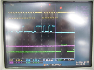
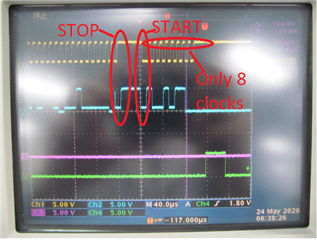
When a write or read process is performed in I2C communication, the slave side fixes the SDA to Low. As a countermeasure, a command to read the conversion completion in ADS 1119 was added before reading the AD conversion, but an error recurred. Please tell me if there are any measures. I will answer any questions about the environment and software. Also, if this error continues, I am thinking of changing to ADS 112 c04, but will the same error occur?

  • Hi 6569991,

    The ADS1119 uses standard I2C protocol.  The same interface is used on the ADS112C04. The communication and timing is shown in the ADS1119 datasheet.

    I'm not clear as to what you are saying is an issue.  After the I2C start condition occurs, the first initial 8 clocks are the 7-bit address followed by the R/nW bit.  The response by the ADS1119, if addressed properly, will be the ACK that occurs during the 9th SCL clock.  The ACK is SDA pulled low by the ADS1119.  After the 9th clock the ADS1119 will release the SDA and further communication from the primary device will continue with the next 8 SCLs followed by the 9th for the ACK.

    If you are having issues with the communication, the best method for troubleshooting is an oscilloscope or logic analyzer probing the SCL and SDA pins.  If you can capture shots of the communication I can help with troubleshooting the communication.

    Best regards,

    Bob B

  • Hi Bob

    I'm not good at English, so please tell me if it's hard to understand.

    I am the one who took over the problem of the person who asked the following URL.

    https://e2e.ti.com/support/tools/ccs/f/code-composer-studio-forum/908194/ccs-ads1119-i2c?tisearch=e2e-sitesearch&keymatch=ADS1119


    Suddenly, I made a loop to monitor DRDY before reading AD conversion and read registers until it became High, and I thought that the error disappeared and was solved, but after about 2 months, the same error appeared again.

    If you have any questions about the source code or environment, I will answer them, so please help me find the cause.

  • Hi 6569991,

    From the previous post that you referred to, the person claimed the communication issue was resolved.  Unfortunately it is not clear to me what was done to resolve the issue.

    Based on the previous discussion, I will assume that the register 1 DRDY bit is being monitored and goes low and stays low.  If this is the case, are you using continuous conversion mode or single-shot mode?

    It is possible that if conversions halt, the ADS1119 has received some form of transient that has reset the ADS1119.  The transient could be on the power supplies or it could be on the analog inputs.

    If the ADS1119 resets due to a transient, the conversions will halt and will reinitialize the registers to the default values.  One method that can be used in code is to issue a loop that runs for a period of counts that if runs longer than the time of one conversion period will call a diagnostic function that will read the ADS1119 register values to see if the settings are default values.  This will tell you that the device has reset and that you need to reconfigure and restart the conversion.

    It the ADS1119 is resetting as I suspect, then the transient should be prevented from entering the ADS1119.  This may require additional components at the device inputs such as TVS diodes and ferrites.

    Best regards,

    Bob B

  • Hi Bob

    Sorry for the late reply.

    When the DRDY bit of register 1 is being monitored and becomes low and remains low, the mode is using single-shot mode.

    Try to determine if there is a transient on the power supply or analog input.

  • In the additional question, it said that the transient phenomenon might have entered ADS 1119 and reset, but is there any change in ADS 112 c04, that the transient phenomenon is less likely to occur than ADS 1119, or that the noise is stronger?

  • Excuse me for asking so many questions.
    Instead of an error occurring during conversion, an error occurs when the READ or WRITE command is executed and the IC is accessed. Does the noise of the power supply or analog input have anything to do with this problem?

  • Hi Kazuya,

    If noise or a transient event is affecting the ADS1119, it would also affect the ADS112C04.  The ADS1119 is a reduced capability of the ADS112C04.

    As I had mentioned before, when the DRDY bit stays low, there could be something that causes the device to reset and halts the device operation.  This can be checked by reading the register contents to see if the values are still the values configured or if they are the default values.

    Based on the additional information, it is possible that something else may be happening.  If you are using single-shot mode it is possible that the START/SYNC command was not executed to start a new conversion.  When you read the conversion data the DRDY bit goes low.  For the DRDY bit to go high, a conversion must complete.  In single-shot mode, the START/SYNC command must be issued for the conversion to start.  When the START/SYNC command is sent to the ADS1119, the device should ACK the command write.  If it responds with NACK, then the conversion will not start and the DRDY bit will always stay low.  Are you checking for ACK/NACK and responding to a NACK condition appropriately?

    Best regards,

    Bob B

  • Hi Bob

    Try to determine if the device is reset.

    When the START/SYNC command mentioned earlier is sent to ADS 1119, does the device sometimes NACK the command write?
    Does it operate other than I2C protocol?
    Also, in the case of NACK, I would like you to tell me the appropriate measures.
    Does the noise affect the NACK?

  • Hi Kazuya,

    You can determine if the device has reset by reading back the register contents.  All communication to the ADS1119 follows the I2C protocol and the timing is in the datasheet.

    As far as the NACK, the host may not issue an ACK (but instead a NACK) if reading from the ADS1119 device and the byte returned is the last in the sequence.  The ADS1119 should always respond with an ACK when being written.

    If you see that a NACK is showing where you expect an ACK, then you need to respond appropriately.  The first step is to repeat the command.  If repeated responses are still showing NACK, then user intervention is required. 

    If noise is present in your system, especially on the SCL, it is possible that an incorrect address is being sent or incorrect commands.  You should always monitor the I2C communication in your code to appropriately handle any errors.

    Another potential issue can be due to using the wrong values of pullups on the SDA and SCL lines.  If you use a large resistance (4.7k or greater) and the SCL frequency is 400kHz or faster, you may not have a strong enough pullup back to the logic high.  These signals can be monitored with an oscilloscope to make sure that the timing is not delayed to to charge/discharge of capacitance of the I2C signal lines.

    Best regards,

    Bob B

  • I will talk about the error that is happening now.

    The image of the oscilloscope above shows SCL in yellow, SDA in blue, and error detection in green.

    It specifies ADDRESS as per I2C protocol and sends a WRITE or READ command.
    On the way, the SLAVE side stuck the SDA with LOW.

    Is there an appropriate action for these problems?

  • Hi Kazuya,

    The communication is invalid.  Note in the marked image below that the 9th SCL clock is never issued for the ACK/NACK.  This is not an issue with the ADS1119 but rather something with the micro.  Perhaps something is missing in the code to complete the last transfer.

    Best regards,

    Bob B

  • Hi Bob

    ・I don't know what is missing, so please tell me if you have a similar problem.
    ・Is it correct that the SLAVE side sets the SDA to LOW when the above error occurs as a movement?
    ・I am currently using the same software and hardware and running multiple units, but only two of them have this kind of error, so I am thinking of an error caused by hardware, but is it wrong?

    Best regards

    Kazuya.O

  • Hi Kazuya.O,

    The SCL input to the ADS1119 is an input only pin on and cannot drive the clock.  The micro must drive the SCL and there is the 9th SCL missing in the previous scope plot.  The SDA will be holding low if the previous data was ACK acknowledged.  To release the SDA from ACK, the 9th SCL is required from the micro.

    So the problem is you are missing the 9th SCL transmitted for the ACK/NACK from the micro.

    Best regards,

    Bob B