This thread has been locked.

If you have a related question, please click the "Ask a related question" button in the top right corner. The newly created question will be automatically linked to this question.

ADS1247: Single-ended measurement with ADS1247

Part Number: ADS1247

Hi there,

I am trying to take a single-ended measurement with an ADS1247, but whatever I do it always returns the same value.

Here's my schematic:

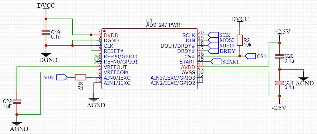
I have set the registers on the ADS1247 as follows:

  • PGA=1
  • Data output rate is 5 sps 

The process I'm using to read data from it (in pseudocode) goes something like this:

(START is pulled high long before this code runs and never goes low)

  • Pull #CS low (enable SPI)
  • Send command RDATA (0x12)
  • Pull #CS high
  • Wait for #DRDY to go low
  • Pull #CS low
  • Send command NOP (0xFF) recording returned byte in variable0
  • Send command NOP (0xFF) recording returned byte in variable1
  • Send command NOP (0xFF) recording returned byte in variable2
  • Pull #CS high

When I look at the data returned, the three values are always 0x80, 0x00 and 0x00 respectively.  The voltage input at VIN on the schematic fluctuates around 70-100mV.

I know that SPI communications are working correctly as I can read back the registers I've written and they match.  I've tried using the self-offset calibration, applying a mid-supply bias to AIN1 and turning on the internal reference, but nothing seems to make any difference.

I'm positive I've done something stupid.  Can you point me in the right direction?

Many thanks,

Foz

  • Hi Foz,

    Can you provide the full register settings that you provide to the ADC?

    Also, why do you issue the RDATA command before DRDY has gone low? I would have expected you to issue the RDATA command, followed by 24 SCLKs after DRDY goes low.

    -Bryan

  • Hi Bryan,

    Thanks for the response.

    The full setup of the ADC (which happens before the loop I detailed in my original post) is:

    • Power on
    • Wait for 20 milliseconds to give PSU capacitors time to charge
    • Pull #CS low
    • Send RESET (0x06)
    • Wait for 1 millisecond
    • Send SDATAC (0x16)
    • *Write register 3 to gain=1, sample rate=5sps (commands 0x43, 0x00, 0x00)
    • Send SYNC command (0x04, 0x04)
    • Wait for 200 milliseconds (to give the ADC time to settle - unnecessary I'm sure)
    • Pull #CS high

    I've tried setting few other registers, but at this moment, that's all that's happening.  Whenever I write to a register, I only write a single register at a time to be sure that I'm not overwriting anything important. 

    As to why I'm issuing RDATA before DRDY has gone low, that's simply because I'm a dumba$$ and clearly can't read instructions properly.  I've changed that now (DRDY goes low, send RDATA, send 24 SCLKs) and the returned values remain at 0x80, 0x00 and 0x00.

    My application for the ADC is measuring the output of a peak detector circuit, which takes a few milliseconds to charge (see image below, I'm measuring the blue trace).  I need to ensure that measurements take place at very specific times.  Do you think I should be issuing a SYNC command at the time I want the measurement to start, followed by RDATA once DRDY has gone low? 

    Thanks for your help & time,

    Foz

  • Hi Foz,

    Do you have the internal reference enabled? I did not see this in your initialization routine, but since you do not have an external reference connected then you must have to use the internal reference.

    You can probe the REFOUT pin to make sure the internal VREF is turned on. If it is not, then you have some digital communication issues.

    If you can turn the VREF on, then I would apply a 1V signal to the ADC inputs with the PGA = 1 and see if it converts correctly. If not, please send me the ADC code in hex. Also make sure that the signal source is referenced to the same ground (AGND) as your PCB.

    The SYNC command can be used, as well as the START pin, to control when the conversion period begins. The SYNC command timing is shown in Figure 79, while the START pin timing is shown in Figure 70. Note that the ADS1247 takes multiple samples over the entire conversion time, so you are not taking a snapshot of a single point in time but instead an average over a longer time period. I just wanted to make sure this was clear.

    -Bryan

  • Hi Bryan,

    Apologies for the slow response.  Turned out I had another problem - the positive voltage regulator that was supplying power to the ADC had failed.  Fixed now.  I only realised that it had broken because I scoped VREFOUT and saw it was only putting out about 500mV.

    Many thanks,

    Foz