This thread has been locked.

If you have a related question, please click the "Ask a related question" button in the top right corner. The newly created question will be automatically linked to this question.

DAC8742HEVM: Problem with test transaction via DAC8742HEVM GUI from DAC8742HEVM to DAC8742HEVM

Part Number: DAC8742HEVM
Other Parts Discussed in Thread: USB2ANY

Hello, dear friends.

I have some problem with connecting two DAC8742HEVM to each other.

I'm using two DAC8742HEVM with SPI & HART interface. I try to transmit data from DAC8742HEVM №1 to DAC8742HEVM №2 with HART mode on UART interface.

I did the following actions:

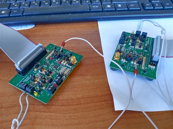
1) I connected MODIN module #1 with MODOUTmodule #2 and MODIN module #2 with MODOUT module  #1;

2) I connected both modules to different PC with USB2ANY;

3) I connected modules with two PC with DAC8742HEVM GUI;

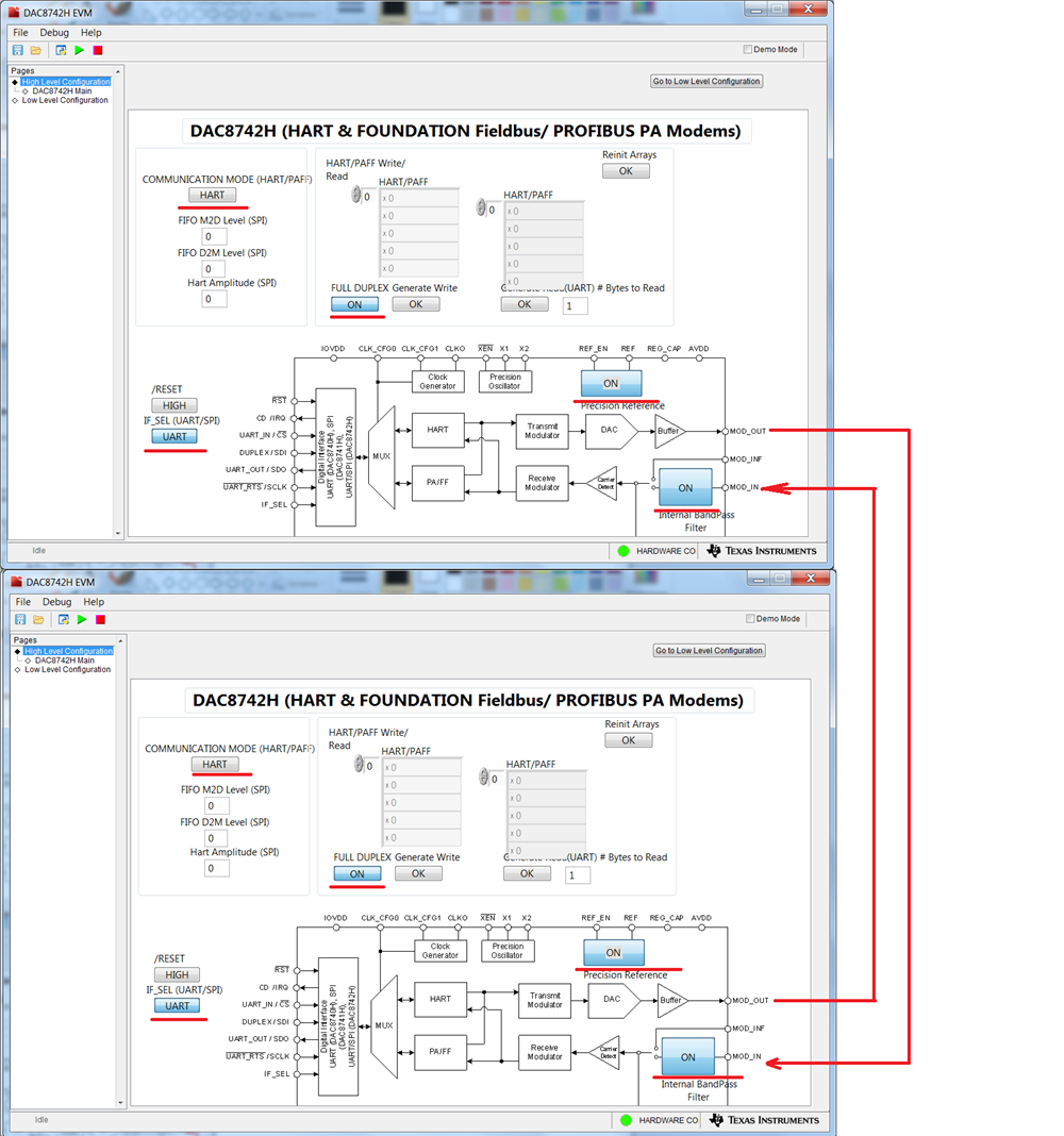
4) Enabled “full-duplex”, enabled “Internal bandpass filter, enabled “Precision reference” in both DAC8742HEVM GUI;

5) Wrote value and Click “generate write“ in GUI N1  and then “generate read“ in GUI N2  

And I’m receive “FF” all time from any value.

If I connect AGND Module №1 to AGND Module №2 I’m receive “00”

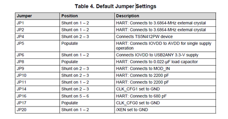
Jumper settings in default position in both modules.

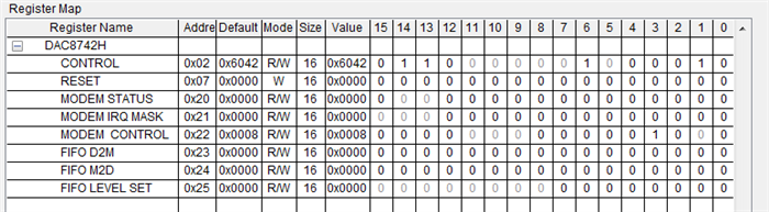
Register map in default value in both modules.

Do you help me, what I’m doing wrong?

P.S.

I take a test transaction data with HART mode on UART interface with one Module: connecting MODIN to MODOUT, switch ON “full-duplex”, switch ON “Internal bandpass filter”, switch ON “Precision reference”. I’m clicking “generate write“ and then “generate read“, and it’s work correct.

  • Sergey,

    I would first start to debug this problem separately with one EVM at a time. You'll need an oscilloscope to check this, but start by looking at the EVM output to see if you can find the modulated signal. 

    I would also just use a multimeter and just check the power supplies and reference voltages just in case.

    Joseph Wu

  • Sergey,


    Actually, one test you can try is to have the EVM talk to itself. In that case, you would attach a wire from MODOUT to MODIN. The connections come out of the EVM at terminal J7 on the right side of the board.

    Then you can enable the reference by clicking on the Precision Reference box in the GUI block diagram. Verify that you can measure a 1.5V reference at the REF test loop. The GUI should enable Full Duplex and the Internal BandPass Filter. IF_SEL should be set to UART

    Then you can enter 5 bytes to test the write. After entering bytes, you can select the generate write button. To check the read, you can select the “(UART) #Bytes to Read" field and enter in the number of bytes (5). Then you select the generate read button and the read bytes should appear in the console.

    Let me know if this works. I've tested it on my board and it seems fine. If you are able to do this for each EVM, you should be able to do this combining the two.

    Note: I would have posted images of the GUI in this, but after the "upgrade" of E2E, I can't seem to do it right now. Once I figure it out, I'll post back.

    Joseph Wu

  • Sergey,

    I just noticed that at the end of your post, you've tried this and that had worked. When you put the two EVMs together, can you start by connecting the grounds on the two boards?

    Joseph Wu

  • Yes, I already connected each of the modules to itself. Separately, they work and I get through the GUI the values that I sent. This means that both modules are good and they are working correctly.

    Now, I connected ground AGND # 1 and AGND # 2 (on photo) and checked their connection with a multimeter.
    I switch ON “full-duplex”, switch ON “Internal bandpass filter”, switch ON “Precision reference” in both GUI.

    I write value and click "Generate Write" in module #1.
    After that I click "Generate Read" in module #2. ( already chose the number of bytes in the “(UART) #Bytes to Read")
    I recieve "00" in all registers.

  • Sergey,

    I'll need some time to test this myself. I'll get back to you once I get another EVM.

    Joseph Wu

  • Sergey,


    I was able to get it to work, but it did take some time to get some transmissions through. I'm not sure why it I didn't get the communication right away, but I did have a few notes on how I tested it. Below are my comments.

    • I started with with 1-way transmission. Start with one EVM as a transmitter and the other as a receiver. This way, there's only one direction to debug.
    • I needed the ground between the devices. There seemed be a lot of noise between one computer to the other (one EVM was connected the power outlet, while the other was connected to a laptop, without power).
    • I set up transmitter first. I first connected the output to the input of the same EVM before connecting to the second EVM. I wanted to make sure the transmitter could receive the output.
    • Use an oscilloscope to monitor the output signal. It helps to see the output is coming out of the transmitter. I looked at this before I connected the output to the input of the other EVM.
    • Set up # of bytes to be read in the GUI.
    • Use SPI for receiver IF_SEL. I'm not sure if this is important, but I was able to get this one to work and the data I read back was correct.

    I had some problems putting images of the GUI into this post. If I can, I'll follow up with some images.

    Joseph Wu

  • Joseph,
    I tried to replicate your experience and I was able to send the value.
    However, when the value is transmitted, some service bytes appear.
    For example:
    1) I pass the value "x6", then on the second GUI I get 2 registers:
    "x1106"
    "x200"
    2) I am sending:
    "x6"
    "x4"
    I get:
    "x2106"
    "x1004"
    "х202" - different each time (202, 203, 204, 206)
    3) I am sending:
    "x6"
    "x4"
    "x3"
    I get:
    "х3006"
    "x2004"
    "x1003"
    "x305" - different each time

    I found a similar topic on the forum, but using the SPI protocol, they explained that "x200" and similar values ​​are the value for the end of the transaction. But it is different every time, even if I pass the same values.

    I also figured out that IF_SEl  does not affect at the sending module. Switched UART / SPI modes, but got the same values.

    I am assuming that the transmission is using the SPI protocol, not the UART.
    Is it so? Is it possible to connect modules via UART?

  • Sergey,


    For the SPI communication, I think what you are seeing is correct. The data that is being read back is the register for FIFO_M2D. For each data that is being sent back the first four bits indicate the FIFO level. For example, if you send

    0x06 0x04 0x03

    The read from FIFO_M2D will indicate the read as:

    0x3006 0x2004 0x1003

    With the first four bits as 3, 2, and 1 indicating where the read is in the FIFO buffer. At the end of this read, you would have finished the read of the FIFO and the last read would give you 0x0200. The first byte of 0x02 indicates that the FIFO has been completely read out. The bit for 2 in 0x02 indicates that the FIFO is empty. The last byte is data and it is from the FIFO, but the FIFO is cyclic and is probably from a previous read. It can be ignored because you've already read out the data from the FIFO.

    For the transmitter, it doesn't matter if the device is in SPI or UART mode. For the receiver, I have only been able to get the device to collect data with SPI. At this point, I'm not sure what it is that the GUI is missing as a receiver when using it in UART mode.


    Joseph Wu

  • Joseph,
    thanks for help, I will try to figure it out