This thread has been locked.

If you have a related question, please click the "Ask a related question" button in the top right corner. The newly created question will be automatically linked to this question.

ADS1294: I would like to inquire about functions and configuration related to ads1294ic.

Part Number: ADS1294

Hello. I have a question about ads1294ic.

1. I'd like to know the purpose of RLDREF (PIN 60) and VCAP1,2,3,4.
For RLD, I understood that additional ECG signal input and OUTPUT FEEDBACK are used for CMRR removal, but I wonder how RLDREF is used here.

2. AVDD1 (PIN 54) and AVSS1 (PIN 53) have different naming, so I'd like to ask if there's any difference between AVDD and AVSS.

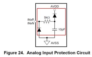
3. You are trying to configure PROTECTION CIRCUIT of ECG INPUT PIN, but the circuit configuration of DATASHEET and EVM is different.
Please check which circuit should be configured. (If you need to follow DATASHEET, please recommend the type of diode or product as well.))

4. I understand that IC thinks it's one person's ECG information even if more than one channel comes in, but I'd like to ask if it's possible to judge CH1 and CH2 as someone else.


Thank you.


  • Hi,

    Welcome to the E2E forum. Thank you for your post.

    1. The VCAPx is the bypass capacitors pins for the internal analog circuitry. The reference voltage for the RLD can be generated internally ([AVDD+AVSS/]2) by the device or provided externally through the RLDREF pin.

    2. The AVDD1 and AVSS1 supply the charge pump block and has transients at the fCLK frequency. It is recommended to use a star connection between AVDD1 and AVSS1 to AVDD and AVSS. Please refer to the power supply recommendations in the datasheet for further information.

    3. Figure 24 shows the device ESD protection and not the ECG patient protection. The requirement for patient protection varies from application to application. You will need to design the input protection circuitry for your application.

    4. This device is mainly used for multi-lead ECG applications. I am not familiar with how to accomplish your design requirement.

    Thanks

    -TC

  • Thank you for your answer. In addition, there are questions for answers 2, 3, and 4.

    2. I don't understand that AVDD1, AVSS1, AVDD, AVSS should be connected to STAR CONNECTION. Can you tell me the specific method?

    3. I understand that the ECG signal input need to add a noise rejection filter. In Figure 24 (DATASHEET) and Figure 7 (SBAA188 EVK circuit), the RC filter has a different value, which value should I use?
    And can I use ARRESTER or TVS for the diode in Figure 24?

    4. I currently try to measure two ECGs with one IC. I wonder if it is possible to measure each person when using CH1 and CH2.(Person 1-CH1, Person 2-CH2)

    Thank you.

  • Hi Dong-Yeong,

    Please see my comment below for your questions. 

    2. Please refer to Figure 109 in the datasheet for the layout example for the device.

    3. Please see the thread below for the RC filtering needed for each input electrode.

    e2e.ti.com/.../ads1298-rc-filtering-question

    As stated previously, Figure 24 shows the internal ESD protection circuitry for the device. These internal voltage protection diodes are there to protect the device from large input voltages or EOS events. External protection is still necessary for patient protection. Please refer to the link below for some helpful discussion on the protection circuit.

    e2e.ti.com/.../882080

    4. This is an interesting ECG application. We have not seen the device used in such a configuration. This will most likely be an ac-couple input single-lead ECG since the RLD will typically bias the patient.

    Thanks.

    -TC

  • Thank you for your answer.

    I have answer number 4 and a separate question.
    1. I know that ch1 and ch2 cannot be used by others, but I wonder what the difference between normal ADCIC and ADS1294 is if RLD is not used. And I'd like to ask if I can use the rest of the channel as a regular ADC.
    2. Also, I wonder if impedance 50 ohm matching is required for each line from ecg and ref input or diff matching such as 90 ohm or 100 ohm.

    Thank you.

  • Hi Dong-Yeong,

    1. You can use the rest of the channel as a regular ADC for your application if needed. However, the ADS1294 is a simultaneous sampling ADC, so you will not be able to set the output data rate independently for each channel. 
    1. There is no 50-ohm impedance matching required. In ECG application, the electrode interface (typical Ag/AgCl wet-electrode) is usually modeled with a 51kΩ resistor in parallel to the 47nF capacitor. It is important to keep the contact impedance of the electrodes and the mismatch between electrodes to a minimum for getting the best ECG signals.

    Thanks

    -TC