This thread has been locked.

If you have a related question, please click the "Ask a related question" button in the top right corner. The newly created question will be automatically linked to this question.

DAC161S997: DAC is not giving required current at output

Part Number: DAC161S997

Hi,


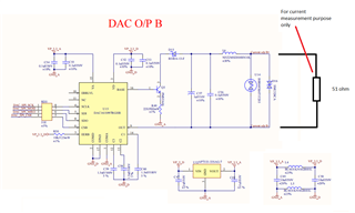
We are using DAC161S997RGHR in our 4-20mA converter application. We have designed the schematic as per datasheet but we are not getting current output. We have used 51 ohm resistor across DAC output to measure current. As per ohms law we should get 1V across this resistor when current is 20mA and 200mV when current is 4mA. But We are constantly getting 0.85V across this resistor irrespective of any data on SPI bus.

Attached is our schematic. Can you please review and let us know if we are doing it correct.

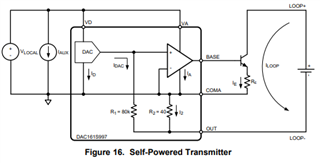
VP_3.3_A and VP_3.3_D are locally supplied (self powered) and only the current loop is loop powered. Do we need to send GND_D to loop receiver?

Regards,
Ramesh Shinde

  • Ramesh,


    The loop power should be isolated from the DAC161S997 power. So you shouldn't send the GND_D to the loop. Often, I refer back to Figure 16 in the datasheet. I would post that here, but I'm having a hard time inserting images into E2E for now. Pull up the datasheet, and I'll refer to that figure.

    The LOOP supply ground (OUT,LOOP-) must be floating with respect the the device ground (GND, COMA). In this way, OUT will be allowed to drop slightly below COMA. Note that the voltage difference will be R2*I2. R2 is the internal 40Ω resistor and I2 basically is the loop current (really the loop current is IE+IDAC which is close to IE).

    Looking at your schematic, you have analog and digital grounds and analog and digital supplies. I would remove the inductors and use just a single supply and single ground. That would simplify your schematic. Then I would start making some measurements with a precision multimeter to figure out where your current is going.

    In particular I'd measure the following:
    Voltage from BASE to GND_A
    Voltage across the emitter resistor
    Voltage from OUT to GND_A
    Voltage from LOOP+ to GND_A

    I'd also check the VCE voltage of Q3 and the voltage drop across D15 just to be sure.


    Joseph Wu

  • Hello Joseph,

    Thanks for you suggestions. I was on leave for last few days, hence did not replied back. I will go through all your suggestions in next couple of days and update you.

    We have local MCU, ADC and RS485 converter on the same board. We are using same GND_D as a reference ground for all these circuits. Floating ground, does that mean all the MCU, ADC and RS485 converter should also have floating ground. GND_A and GND_D is acting as local ground to all these circuits including DAC?

    Regards,

    Ramesh Shinde

  • Ramesh,


    In my previous post, this is Figure 16 from the datasheet that I was referring to:

    For this setup, the DAC power and loop power should start out floating from each other. When connected, the LOOP- is driven by OUT, and thus ends up below the DAC ground. Therefore, the voltage of OUT will be below the ground voltage of COMA by a voltage of I2*R2.

    I don't have a block diagram of your system, but I would guess that your MCU, ADC, and RS485 converter all will be on the same ground as the DAC, and anything else on loop power will be on a separate ground.

    I would note that the GND_A and GND_D should be the same. Generally, I wouldn't separate them and I would replace L5 with a short to be sure.


    Joseph Wu

  • Hello Joseph,

    Please find attached our application block diagram. I am powering this circuit with external 12VDC power supply, but not supplying power supply ground. Effectively this power supply will be floating. DAC COMA line acts local ground (floating ground) to this circuit. Loop current is measured at receiver end across 51 ohm resistor. So equivalent voltage will be V = I x R. That is at 4mA, voltage across 51 ohm resistor will be 0.2 approx. and at 20mA, voltage across 51 ohm resistor will be 1V approx.

    Hope this circuit will work.

    Please provide your suggestions.

    Ramesh Shinde

  • Ramesh, 

    So the way that you have it set up should be ok. Basically the loop power supplies the power to the device (and other devices) through the LDO. This is similar to the block diagram shown in the datasheet. 

    Again LOOP- will not have the same voltage as the DAC ground. 

    Joseph Wu