This thread has been locked.

If you have a related question, please click the "Ask a related question" button in the top right corner. The newly created question will be automatically linked to this question.

ADS1282: Bipolar Vs unipolar supply

Part Number: ADS1282
Other Parts Discussed in Thread: LM27762

Hi TI, 

I am currently designing a datalogger using the ADS1282 (and the ADS1282H) and i have a questions regarding bipolar Vs unipolar supply. 

Which would you advise i use and why? 

I initially wanted to use unipolar supply (0-5V) and then bias my input channels to 1/2 VCC, but my supervisor suggested that there may be benefits for using +-2.5V instead as noise coupled from the biasing circuit is eliminated. I notice that your examples in section 9.2.1 of the datasheet use bipolar supply too.

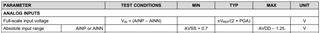
I also thought that distortion may occur as signals approach the +5V rail, would this be the case? And would the same sort of distortion be apparent in a bipolar system as the signal approaches the rails? 

Thanks for any advice and please feel free to add any further thoughts regarding the choice of supply topology.

Jon 

  • Hi Jon,

    Welcome to the TI E2E Forums!

    From a performance perspective, I don't think there will be much of a difference between the bipolar and unipolar configurations. In the bipolar configuration you have to provide a -2.5V supply; however in the unipolar configuration you have to provide the mid-supply bias. While a biasing circuit will have output noise, this noise should appear as a common-mode signal and be rejected by the differential inputs of the ADS1282.

    If you already have one or the other required potentials then you might just go with the configuration that requires adding fewer components. If you need to generate the bipolar supplies, then I'd suggest using the LM27762 since it only requires a single supply (in the range of 2.7 to 5 V) and you don't need to add LDOs to filter the supplies because these are integrated.

    Whether you go with the bipolar or unipolar supply configuration, the internal PGA of the ADS1282 will have input range limits with respect to the AVDD and AVSS supply rails. For the input range you cannot exceed the maximum differential voltage of +/- 0.5 * VREF / PGA. For the absolute input voltages on AINP or AINN, you must be 0.7 V above the negative supply (AVSS) and 1.25 V below the positive supply (AVDD) to avoid distortion from the PGA. Because of this input range, it is common to bias input signals to AVSS + 2.225 V (or thereabouts) to allow for the maximum input differential voltage swing.

    NOTE: There is also an output voltage range limitation for the PGA. The PGA outputs should remain 400 mV away from either supply rail to avoid saturation. However, in practice if the input voltage is biased near AVSS + 2.225 V (no more than 3.35 V above AVSS and no less than 1.65 V above AVSS), then this should not be an issue.


    Best regards,
    Chris

  • Thank you very much for the informative answer Chris.