This thread has been locked.

If you have a related question, please click the "Ask a related question" button in the top right corner. The newly created question will be automatically linked to this question.

AMC7836EVM: Can't READ/WRITE from/to any of the devices register.

Part Number: AMC7836EVM
Other Parts Discussed in Thread: AMC7836

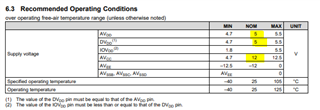
I'm trying to read/write from the AMC7836 registers.  I'm using the SDM-USB-DIG platform and TI's WIN 7 GUI Software.  The VDUT is 3.3V but the SPI signals are only 1.8Vp-p.  The AMC7836 requires 0.7 * IOVDD ( 0.7 * 3.3) which is 2.31V min for a min logic high.  The Microcontroller (MPS430) on the SDM-USB-DIG states that at VCC = 3V the High Level Output (Voh) = VCC - 0.6V or 2.7V(min).  The voltage level translator between the MCU and the AMC7836 has +3.3V for both VCCA and VCCB.  So I can see no way that the SPI SCLK, SDI, CS signals can only be 1.78V p-p.  Also SDO which originates at AMC7836 also only 1.8V p-p signal level.  How can this be?  What I'm missing here?

  • Upon further review it looks like the voltage translators on the SDM-USB-DIG (TXS0108) B side is connected to 1.8V which makes no sense because there is no 1.8V on the SDM-USB-DIG board only the USB +5V and the regulated +3.3V which supplies the MCU.

  • My bad the voltage translator on the SDM-USB-DIG VCCB side is connected to +3.3V.  The AMC7836 advertises a low power SPI 4 wire interface that operates between 1.8V and 5.5V, so maybe the Logic signal level is okay.  Still the SDO which connects to a pull up in the voltage translator should be pulled to +3.3V since 1) SDO goes into HI_Z when CS =1 and 2) the pull up is connected VCCB which is +3.3V

  • I think I have a defective board or something.  The MCU should be putting out a LVTTL (+3.3V) SCLK, SPI, CS logic levels.  If the Voltage translator uses that for both sides then I should be seeing LVTTL levels signals at the edge connector not 1.8V Logic levels.  And that would make sense because the SDM-USB-DIG is providing +3.3V to the AMC7836 IOVDD pin.  Furthermore if the AMC7836 IOVDD is +3.3V then the SPI signal levels must also be +3.3V, unless the AMC7836 can receive SPI data at 1.8V signal levels with the IOVDD at 3.3V.  

  • Can you confirm the jumper positions you are using? I assume you are using the onboard power conditioning. Can you confirm the voltage on the DVDD, AVDD, and AVCC test points?

    Thanks,

    Paul

  • AVDD, DVDD = +5V (using on board 5V LDO) jumper JP6 pins 2-3

    AVCC = +12V (using on +12V) jumper JP1 pins 1-2

    AVEE = 0V jumper JP2 pins 2-3

    IOVDD = +3.3V (supplied by SDM_USB_DIG) jumper JP7 pins 1-2

    No matter what I do I get nothing out of SDO when controlling it by laptop and GUI.  This would be with IOVDD set at 3.3V and as I've stated the SPI signals that originate from the MCU on the SDM-USB-DIG are only 1.8V???  Now when I control the AMC7836 with my firmware (VHDL) I set IOVDD to 1.8V and the SPI signals all originate from a LVCMOS 1.8V FPGA bank.  Even in this case though there's no SDO.  I believe I should be able to read the device registers without any configuration of the IC.  So I can't confirm the operation of the AMC7836 using the TI software GUI and even with the correct IO to match the SPI logic level there's still no SDO (serial data out).

  • Hi James,

    Just to confirm - you measured the voltage on the test points to double check that the power supplies are actually valid - correct? I just want to confirm if that the power circuit is working.  Your jumpers are correct.  WHen you connect the SDM and launch the software, do you see 3.3V on IOVDD testpoint TP21?

    When you launch the software, do you see that the software is "Connected" or "not connected"?

  • Measured AVDD @ TP19 and U1.50

    Measured DVDD @ TP20 and U1.63

    Measured AVCC @ TP2 and U1.20, U1.57

    Measured IOVDD @ TP21 and U1.1

    Measured AVEE @ TP12 and U1.17

    With 24Vin both DC/DC converters output +14V (U2,U5).  U3 outputs +12V, U4 outputs +5V and U6 outputs the -12V

    With the SDM plugged in and powered by USB, both LEDS on SDM are illuminated, VDUT on SDM is +3.3V and JP7 (on EVM jumper pins 1-2).  This jumper connects VDUT to IOVDD.  Again what doesn't make sense is why the SPI signals that originate from the SDM are 1.8V Logic.  The SDO output from AMC7836 (when in HI-Z state) is clamped to 1.8V?

  • Just to confirm, yes I see +3.3V at TP21 when the SDM is plugged in, powered and I've launched the GUI.  If I don't launch the GUI, there's no VDUT.

  • Paul, I purchased another EVM and the SDM SPI signals are LVTTL +3.3V Logic levels.  I can read and write to EVM.  

  • Hi James,

    I suspect something damaged the EVM or the SDM dig.  Please let me know if you have any other issues.

    Thanks,

    Paul