This thread has been locked.

If you have a related question, please click the "Ask a related question" button in the top right corner. The newly created question will be automatically linked to this question.

Meaning of data from AMC1210?

Other Parts Discussed in Thread: AMC1210, AMC1203

Hello,

I'm working on a project with the AMC1210. At the input from the AMC1210 I apply the signals from the AMC1203 (MCLK and MDAT). I provide a differential voltage of 110mV at the input of the AMC1203. Now I configure the AMC1210 so that it runs with a sinc1 or sinc2 filter and experimenting with the oversampling ratios of the sinc filter unit. I don't modify any other register because I only want to get back the the 110mV that I provided at the input of the AMC1203. I've chosen the 16-bit data representation and communicate via SPI to the AMC1210. Now is my question: how can I find back the 110mV from the data that I'm reading from the AMC1210?

I did some measurements and these are the results:

Sinc1 data:

Sinc2 data:

Thanks in advance!

Mathieu

  • Hello again Mathieu,

    The first thing you need to do across each of these acquisition cycles is adjust the bit shift for 16-bit data formats. This is discussed in the Integrator Unit section of the datasheet on page 22. Essentially modifying the oversampling ratio changes the position of the 16 bits that will enable you to realize the full 16 bit range.

    Resolving codes to voltages from your conversion results is a little more complex than your typical data-converter since the AMC1203's input range and reference voltage are different. But, since we know the device has a +/- 280mV input range and 280mV applied at the input should correspond to a code of 0xFFFF we can define the LSB weight and in turn convert from codes to volts.

    There's two ways you could go about doing this. You could start by looking at the MSB to decide if the data is positive or negative. If you see a 0 in the MSB the data is positive, if you see a 1 the data is negative. Next you apply the weight of an LSB to determine the magnitude. In the positive case you would multiply the value directly by 288mV/(215-1). In the negative case you invert all of the bits, then add 1, then multiply this "straight binary" value by 288mV/(215-1).

    Alternatively you could store the data in a 16 bit signed integer and just multiply the conversion results by 288mV/(215-1) since a signed integer will inherently carry the sign appropriately.

  • Hi Kevin,

    Thank you again for the explanation, it's very helpful!

    For the ease I only apply a positive differential voltage. But I still struggle with the bit shift for 16-bit data formats. Which value should I give it as a function of the OSR? For now I only remained it at zero.

    Should I only use a OSR of 256 for the AMC1210 because the AMC1203 works with a OSR of 256?


    Best regards,

    Mathieu

  • Mathieu,

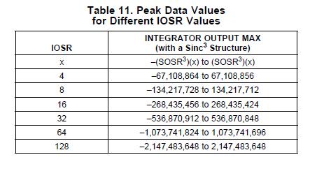
    To be quite honest I haven't had the time to really derive an equation for bit shift as a function of over-sampling ratio - there's a figure in the datasheet that shows the appropriate shift for 3 oversampling ratios

    When I'm doing these things I usually just apply a signal that exercises the full range of the delta-sigma modulator the AMC1210 filter module is connected to and adjust the bit shift until I can reconstruct the full waveform without any clipping or other signal distortion. Typically this is pretty obvious.

    This is something I've been meaning to get to - this is a good opportunity to give it a look. I'll let you know my findings.

  • And one more item of note...

    Mathieu De Zutter said:
    Should I only use a OSR of 256 for the AMC1210 because the AMC1203 works with a OSR of 256?

    The AMC1203 works with any oversampling ratio. If you want to maximize the effective number of bits or resolution of your conversion results you should be operating at an oversampling ratio of 256. This does sacrifice your data-rate, though, since it takes more conversions to get you a result.

    Additionally, this gets into the philosophy of your data-acquisition system. If you'd like to see a conversion result that represents the average value of a signal that is typically very stable a higher OSR makes better since. If you're measuring a volatile signal that you need to know the instantaneous value of with high frequency use a lower OSR.

  • Mathieu,

    The real trick here is to determine the maximum bit width of the conversion result. The first step, then, is to determine the range of values produced by each filter architecture. These are defined by Table 10 in the AMC1210 datasheet. Once we know where the MSB is of the full conversion word we can decide where the 16 bit word LSB is and in turn know how much shift to apply to achieve meaningful 16 bit data.

    Sinc1 : Range = -x to x

    Sinc2: Range = -x2 to x2

    Sinc3: Range = -x3 to x3

    Sincfast: Range = -2x2 to 2x2.

    Where x is the oversampling ratio.

    With the range in mind we must determine the word width for each architecture and each oversampling ratio. This can be defined by:

    Sinc1 : Width = log2(x)

    Sinc2: Width = log2(x2)

    Sinc3: Width = log2(x3)

    Sincfast: Width = log2(2x2)

    Where x is the oversampling ratio.

    Now that we know the maximum word width we must determine where the LSB to know the appropriate shift value...

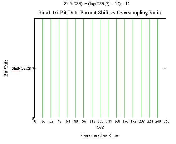
    Sinc1 : Shift = int(log2(x) + 0.5) - 15

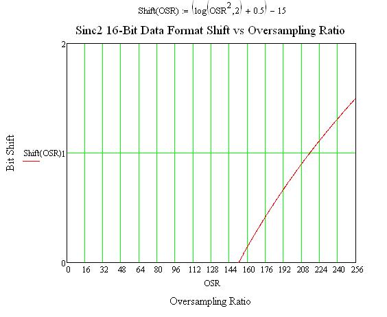
    Sinc2: Shift = int(log2(x2) + 0.5)  - 15

    Sinc3: Shift = int(log2(x3) + 0.5) - 15

    Sincfast: Shift = int(log2(2x2) + 0.5)  - 15

    Where x is the oversampling ratio and 'int' implies integer truncation. Only positive shift values are valid.

    It is of note that as the integrator oversampling ratio increases the shift values will also need to be updated...

    Hope this helps.

  • Hi Kevin,

    Thank you very much for explaining this!

    Best regards,

    Mathieu

  • Kevin,

    You've said that the inputrange of the AMC1203 is ±280mV. That's correct if you look to the recommended operating conditions. But the maximum ratings denote that the analog input voltage have an inputrange of ±300mV. An input of +280mV results in a modulator bitstream of ones and zeros with 87.5% of the time a high signal. So the AMC1210 won't give the value 0x7FFF but a value thats smaller than this. Thus to find back the input voltage of the AMC1203  we need to multiply the value from the AMC1210 with 300mV/(215-1).

    I think this is correct?

    To check this out, I solved the equation (from the number of shifts from the sinc2-filter) equate to zero. The oversampling ratio where no shifts are needed is located at approximately 152. I read the data and it returns me approximately 7890 (differential voltage at AMC1203 = 110mV). Now I multiply this result with 300mV/(215-1). The result is 72.24mV. 

    What am I doing wrong?


    Best regards,

    Mathieu 

  • Hi Mathieu,

    First, yes you've caught me only glancing at the AMC1203 datasheet, and I specified the full scale range incorrectly. The full scale range, however, should be +/-320mV. This is in the table on page 5 of the AMC1203 datasheet labeled "FSR - Full Scale Differential Voltage Input Range"

    We've touched on everything that you need to know to convert the codes to volts, but we haven't really comprehensively tied everything together just yet. In review I wasn't particularly clear that the equation I described before assumed 16 valid bits (15 data bits + 1 sign bit). I'll try to go through the specific case of using a Sinc 2 with OSR 152 and a 110mV differential input voltage applied to an AMC1203, hopefully you can follow along and apply it in the generic case...

    A sinc2 filter output range is +/- x2, as discussed earlier, where x is the OSR. You've chosen an OSR of 152, so we can expect to see results from -23104 to 23104.

    Next, we determine the bit-width of the resulting word, log2(x2), is 14.495855 bits. At this point you should notice that 14.495855 bits (assuming fractional bits could ever exist...) only gets you from 0-23104 and cannot obtain any negative values, so an additional sign bit must also be acquired from the AMC1210 data register (not that we mind in this case since we're forced to get all 16 bits). We know that we'll only see 14.495855 bits of valid data so we should take 16 bits to guarantee the presence of a sine bit (since we're using about half of the codes on both sides of bit 15 - it's going to move). The LSB weight should still be defined by the number of valid bits - not the number of bits we're going to use to fetch our conversion result.

    In general terms there are two ways to calculate LSB size for a bipolar binary two's compliment data converter. Either:

    Vref/(2^(Bits-1)-1) or 2Vref/(2^(Bits)-1)

    But these equations assume the 'Bits' includes the sine bit - which we know our 14.495855 value is already missing. So our equations should look like:

    320/(2^(14.495855)-1) or 640/(2^(15.495855)-1)

    Using either of these values as your LSB weight on a code of 7890 yields ~109.285mV. To really verify the conversion results you'd want to look at more than a single point & average the values.

    This is a challenging device to use - let me know if I need to make another attempt at explaining this...

  • Hi Kevin,

    Thank you for the explaination! I really appreciate it!

    I think that I fully understand it now. Next week i'll do some more measurements to verify it.

    If a negative shift is needed I can shift zeros into the result from the right with the microcontroller. So every zero is a multiply by two. This isn't good for the accuracy but then I can measure with any digital filter and oversampling ratio.

    Thanks for your time.

    Best regards,

    Mathieu De Zutter

  • Hi Kevin,

    I'm finalize my project with the AMC1210 and it seems to be very accurate for measuring voltage! I did a lot of measurements with the different filter structures by vary the OSR and the input voltage at the modulator (AMC1203) from 20,000 mV to 260,000 mV. I have two more small questions:. 

    • I'm reading the 32-bit dataregisters with SPI. The result I get from the AMC1210 I multiply by a factor 0.320/(OSR3-1)  (sinc3-filter). But I've never wondered where the substraction by 1 come from? Can you explain this te me?
    • The same for the formula for calculation the number of shifts needed when a 16-bit data representation is chosen: Sinc3: Shift = int(log2(x3) + 0.5) - 15. Where does the 0.5 come from?

    Best regards,

    Mathieu

  • Hi Mathieu,

    Great to hear you have had success with your project. 

    Mathieu De Zutter said:
    I'm reading the 32-bit dataregisters with SPI. The result I get from the AMC1210 I multiply by a factor 0.320/(OSR3-1)  (sinc3-filter). But I've never wondered where the substraction by 1 come from? Can you explain this te me?

    The equation you have here is a little un-conventional. For the sake of this explanation's relevance for you in things beyond the AMC1210 and oversampling lets look at the more generic form of the equation to calculate LSB weight for a bi-polar data and uni-polar data...

    Bi-polar

    LSBweight = 2Vref / ( 2bits - 1 ) or LSBweight = Vref / (2(bits-1) - 1)

    Uni-polar

    LSBweight = Vref / (2bits - 1)

    In the bi-polar case for a typical system we can resolve voltages from - Vref to Vref and in the uni-polar case we typically can only resolve voltages from 0 to Vref. Bi-polar results are usually in the binary twos-complement format, so our equations have to be modified to compensate for the MSB being used for sign. If you compare the two equations I've given for the bi-polar case you'll notice they're more or less the same value for large number of bits, otherwise the second equation is the 'most correct.'

    The main item of interest here is the (2bits - 1) piece of the equation. This is quantifying how many values we can represent with some number of bits. We have to subtract one to keep the value from rolling over to an additional bit. Consider 8 bits for example... 28 = 256, but what is 256 in binary? 100000000 - a 9 bit wide word. We must subtract 1 to get 255 - the highest value that can be represented with 8 bits.

    Mathieu De Zutter said:
    The same for the formula for calculation the number of shifts needed when a 16-bit data representation is chosen: Sinc3: Shift = int(log2(x3) + 0.5) - 15. Where does the 0.5 come from?

    We need to ensure that we have all of the bits that will be 'moving.' Adding .5 will ensure that we round appropriately to keep all of the relevant bits. Consider the example we went through earlier in this thread where we found a word-width of 14.495 bits - to get all the moving bits we actually need to ensure that we round to 15 bits plus an additional sign bit to get the full word. 

    Forcing all of this into a few equations isn't really natural. It's best to look directly at the range of values that we can achieve based on the digital filter architecture and then consider how many bits we must have to represent these values in straight binary or binary twos-complement.

  • Thanks again Kevin!

    Best regards,

    Mathieu De Zutter