This thread has been locked.

If you have a related question, please click the "Ask a related question" button in the top right corner. The newly created question will be automatically linked to this question.

ADS 1298 ECG FE pin configuration

Other Parts Discussed in Thread: ADS1298

Hi all,

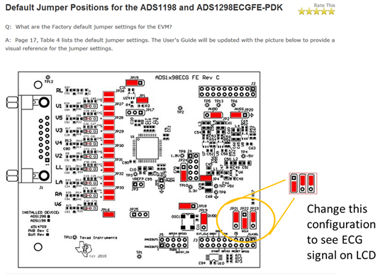
The link below shows the default pin configuration over ADS1298 ECG FE, however when I connect the pins like that I cannot observe any signal on LCD. Moreover when I look at the DRDY I see a 3.3 V high voltage but not toggling. CS also seems high and SCLK is low.

http://e2e.ti.com/support/data_converters/precision_data_converters/w/design_notes/1535.aspx

When I connect the jumpers like below, I see the signal on LCD after loading ECG_NonBios.out and all the signals DRDY, SCLK, CS are OK. Are there anything wrong? If not, then what is the confusion about default pin configuration.

For the configuration on the left (with ECG_NonBios.out loaded) I added the signals below:

1565.DOUT.TIF

5543.DRDY.TIF

1565.SCLK one frame.TIF

6710.SCLK.TIF

By the way, when I build and load my code, I see the signal waveforms below , I couldn't be able to figure out the problem and need professional help:

2766.DRDY2.TIF

Please, please, please help....

Regards...

  • Ekrem,

    Where are you applying your SPI signals to interface the board? JP21 and JP22 just modify the routing of the CS and CONVST signals. The confusion here seems to be that you're controlling the board from another uC board than our EVM-PDK. For our demonstration system the default jumper configuration is correct. Check out the schematic for more details, the "MDK-Interface" section. 

    Your oscilloscope captures would be more helpful for us to debug your problem if they showed all of the serial lines in a single capture, rather than each signal isolated in a separate capture. 

  • Hi Kevin,

    Thank you for your reply. Yes I am using another board EVM5515, I think the configuration 2 (right in my picture) is the correct one for EVM5515 because when I inspect the schematics I realize that CS will be correct for the connection in the right. 

    I figure out my problem and change also CLK_SEL to take it internally which solve my problem. By the way I am not still confident about the behavior of the board and my code.

    Regards.