This thread has been locked.

If you have a related question, please click the "Ask a related question" button in the top right corner. The newly created question will be automatically linked to this question.

Glitch problem with TLC5615 SPI 10 bit DAC


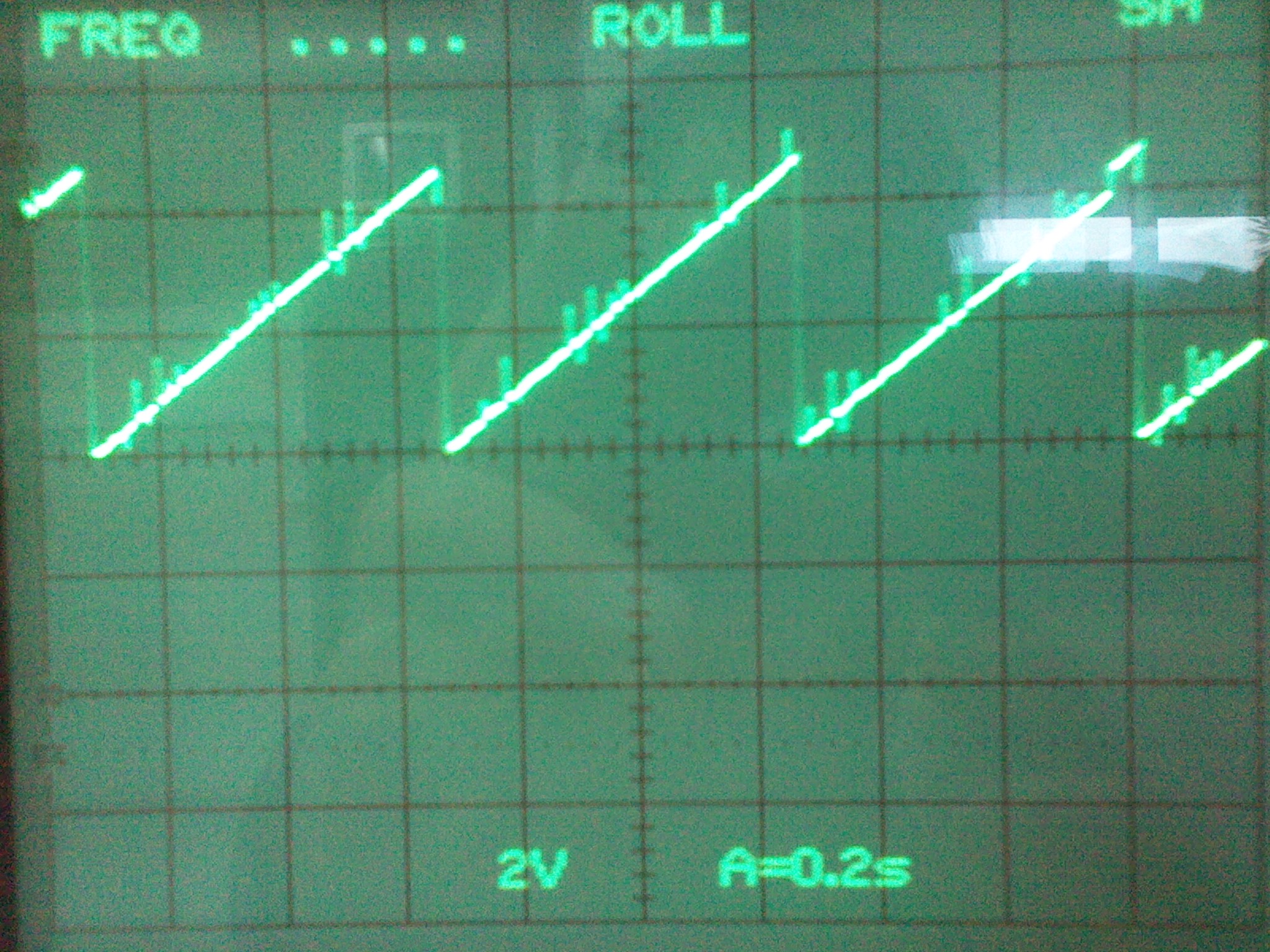
Hi everibody. Just trying to interface a 10 Bit serial DAC (SPI protocol) to a ordinary 8bit microcontroller. I have written the code in assembly and all the timing constraints are respected: However when I try to put a saw-tooth waveform at the DAC output I get the following result:

Where those glitches come from? They seems random, so they are some kind of noise however their amplitude is too high to be conversion noise. The error seems normally distributed...

Please note that the DAC update is 2MHz, way below his maximum value, and the signal generated has a period around 2KHz.

Any help toward the understanding of this effect will be appreciated.

Best regards to all.


  • Hello, and welcome to the E2E Community!

    It would be helpful to have some additional information to go on to understand your problem better. If you can share a schematic / layout for the design that would be an excellent start. If there is any chance that we can discover where these impulses are occurring that would also help find the cause of the problem. Perhaps a capture of the bus latching the DAC word with the output in the same capture.

  • Hi, try with a filter lowpass in the output for to solve your problem with the glitch, but you need to set a Passband Frequency not so low, because if this is very low go to modify you signal of out. Also this filter can to function as a buffer of out.

  • Thanks for your advice Luis.

    Typically glitch energy like this is only associated with R-2R and MDACs where many moving switches cause high glitch energy during a major carry transition. Meanwhile a string DAC will typically exhibit the minimal glitch energy across any code-to-code transition. TLC 5615 is a string DAC that is specified with 5nV-s of glitch transitioning from 0 code to full scale. 

    In general Luis' suggestion is correct, size an R/C filter with the correct time constant to match the period of the glitch energy you observe at the DAC output.

  • Hi everibody. Many tanks for all the inputs I've received regarding the initial problem that I post. In fact a low pass-filter can be used to circunvent the glitch problem. However one must expect some distortion on the output wave format speccially on the high frequency transition. Well I'm updating my initial post not because I tested the low pass filter strategy but because I've used another strategy to send the data to the SPI dac. In my previous post I used the dedicates SPI ports of a 16F74 MCU. In a second strategy I've implemented a bit-banging SPI protocol in another set of pins. Below you can find a screenshot on the results from the former strategy and the later. As you cans see the glitch problem is completly eliminated with this solution. If I have the time (and motivation) I will try to find the cause of the original problem...

    Best regards to all.

       (Using the SPI dedicated ports)

     (by bit-banging)

  • Thanks for the follow up. It's nice to see closure to the problems we see on the E2E Community.

    Should you revisit the problem I'd be interested in seeing a before and after capture of your SPI bus. This could be a phenomenon called "Digital Feedthrough" where high frequency content at the serial inputs can couple into the output even while CS is high through internal stray capacitance.