Other Parts Discussed in Thread: ADS1299
In regard of the ADS1299 EEG-FE, I have checked the diagrams on page 51-2 of the "ADS1299EEG-FE user guide" and still have doubts on how to connect the reference electrode and bias electrode.
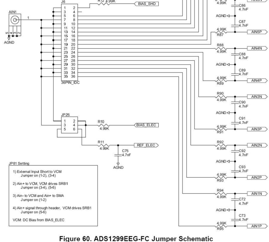
(1) If I have 3 electrodes from right frontal, left frontal and earlobe respectively, which pins of the J6 and JP25 should I connect these 3 electrodes to?
(2) Is the AIN1 pin 1 used as the reference electrode input?
(3) If the jumpers on J6 and JP25 are set as factory default except pin 35-36 on J6, where I connect a single-ended sine wave to pin 36 and connect pin 35 (also connected to AIN1 pin 1) to ground, is the BIAS_ELEC input the one that I can use to connect to a reference electrode? From the diagram, I see the BIAS_ELEC input is connected to the REF_ELEC through R10.
Thank you so much for your help.