


Hi all,
I just study the SLAU513B about ads8881x ADC.
At the page of 12,it describes as below:
The selected value of capacitance for each input of the ADC is set slightly higher than the calculated value
to 4.4 nF if the filter is designed in a common-mode configuration as shown in Figure 8. However, this
design uses a differential configuration for the RC-filter, so a 2.2 nF capacitor is connected across the
differential inputs of the ADC.
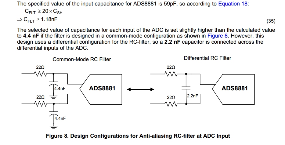
My question is why the differential mode use the value of capacitor half of that in common mode?4.4 nf -->2.2 nf?
Also how about the resistor difference between common and differential mode?
Thanks
Robert
