This thread has been locked.

If you have a related question, please click the "Ask a related question" button in the top right corner. The newly created question will be automatically linked to this question.

ADS7863 w/ Raspberry Pi

Other Parts Discussed in Thread: ADS7863

Is there anyway for this to work? All of the library's that I have tried to use (WiringPi, etc.) are configured for 4-wire SPI and not for the extra CONVST and RD wire. Is there a way to code around this, i.e., somehow connect the clock to another pin. Thanks! 

  • Hi Swanagan Ray,

    Take a look at this app note: http://www.ti.com/general/docs/lit/getliterature.tsp?baseLiteratureNumber=slyt244&fileType=pdf

    The CONVST+RD can be initiated by a timer or GPIO function, but RD needs to see a CLK edge for you to get valid DOUT. Have you tried sending 0x8000 as an SPI transfer out to the ADS7863 with SDO of your Pi device connected to RD+CONVST?
  • Thanks! That got the two communicating. However, it is reading in "junk" values. I am testing the ADC with a 10k-ohm potentiometer. As I move it, the inputted values don't seem to change. If I can't iron it out within the next day, I'll get back in touch. 

  • Cool!

    You might consider changing that pot to something lower in the long term unless you have a buffer in between the resistor and the ADC input.  Regardless, even with a 10k pot, you might not get perfect results but they should not be 'junk'.  Check your data/colock polarity settings.  SDO should be valid on a falling SCLK edge.

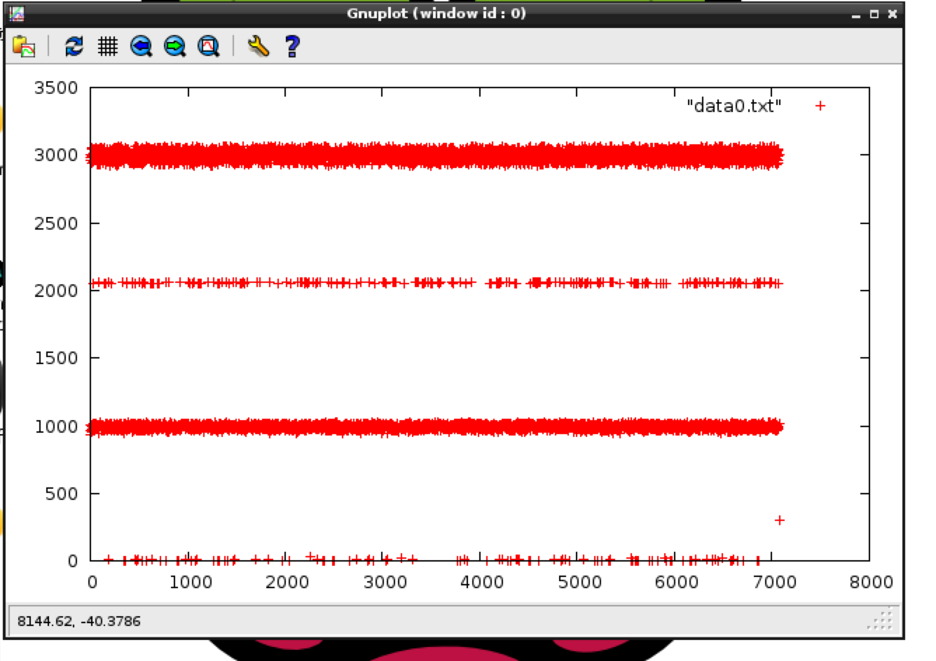
  • Thanks for the info! I have checked the polarity settings and they are correct. However, the problem is that no matter the input signal, the output at the microcontroller is always a set pattern. I tried a 2kHz, 2 V sine wave, square wave and just 2 Vdc. The pattern was still the same. Here is a graph of the values.

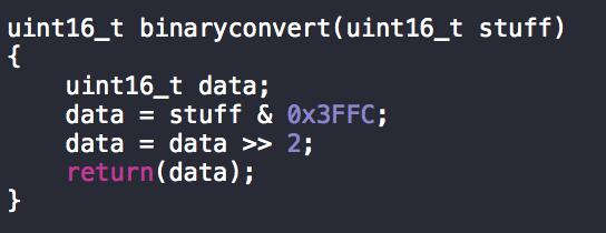
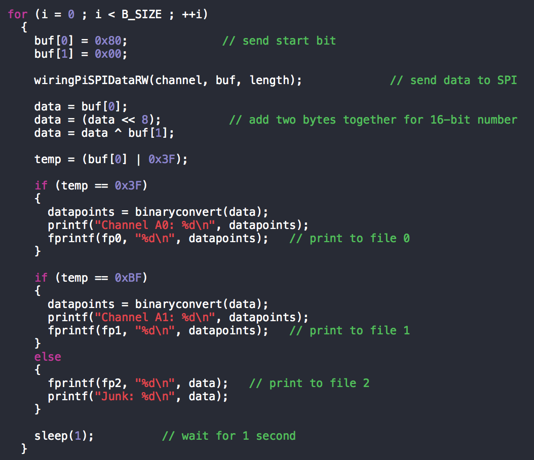
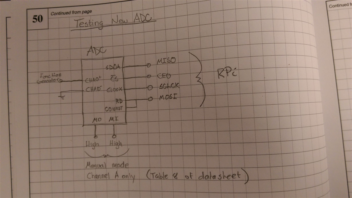
    Also, here is my code and hardware setup.

    It seems that it is identifying which channel is coming in since it always prints A0 to the screen but the values are in the range from 512-4020. Not sure if you can make any sense from this but any help would be appreciated.

    Thanks!

  • Humm...not sure what that data you plotted could be.  Can you grab screen shots using a O-scope or Logic Analyzer showing the SDI/SDO and SCLK?  Also, the A0- input should be taken to Vref or an external 2.5V source if you are driving the input single ended.

  • Sure!

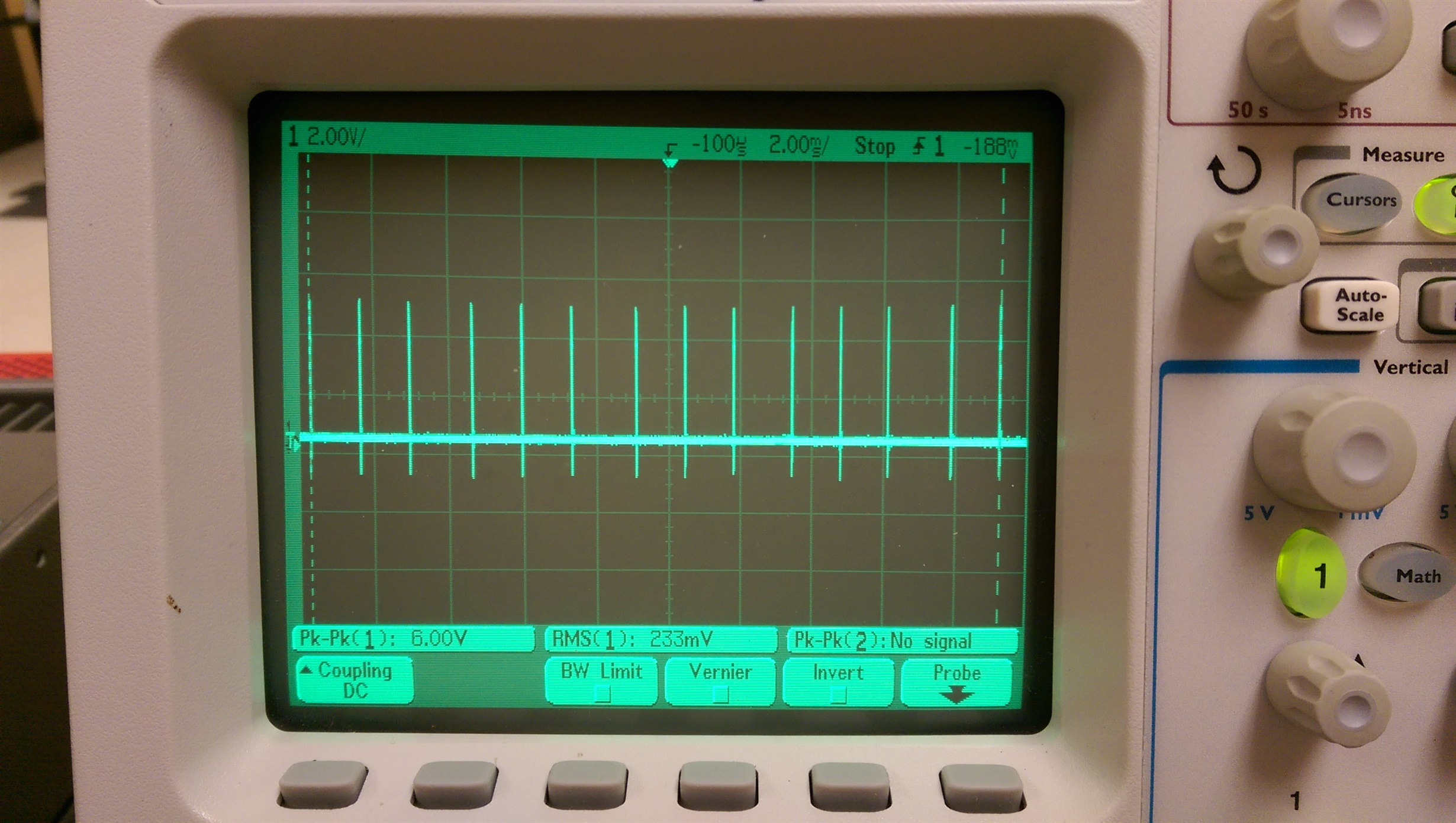
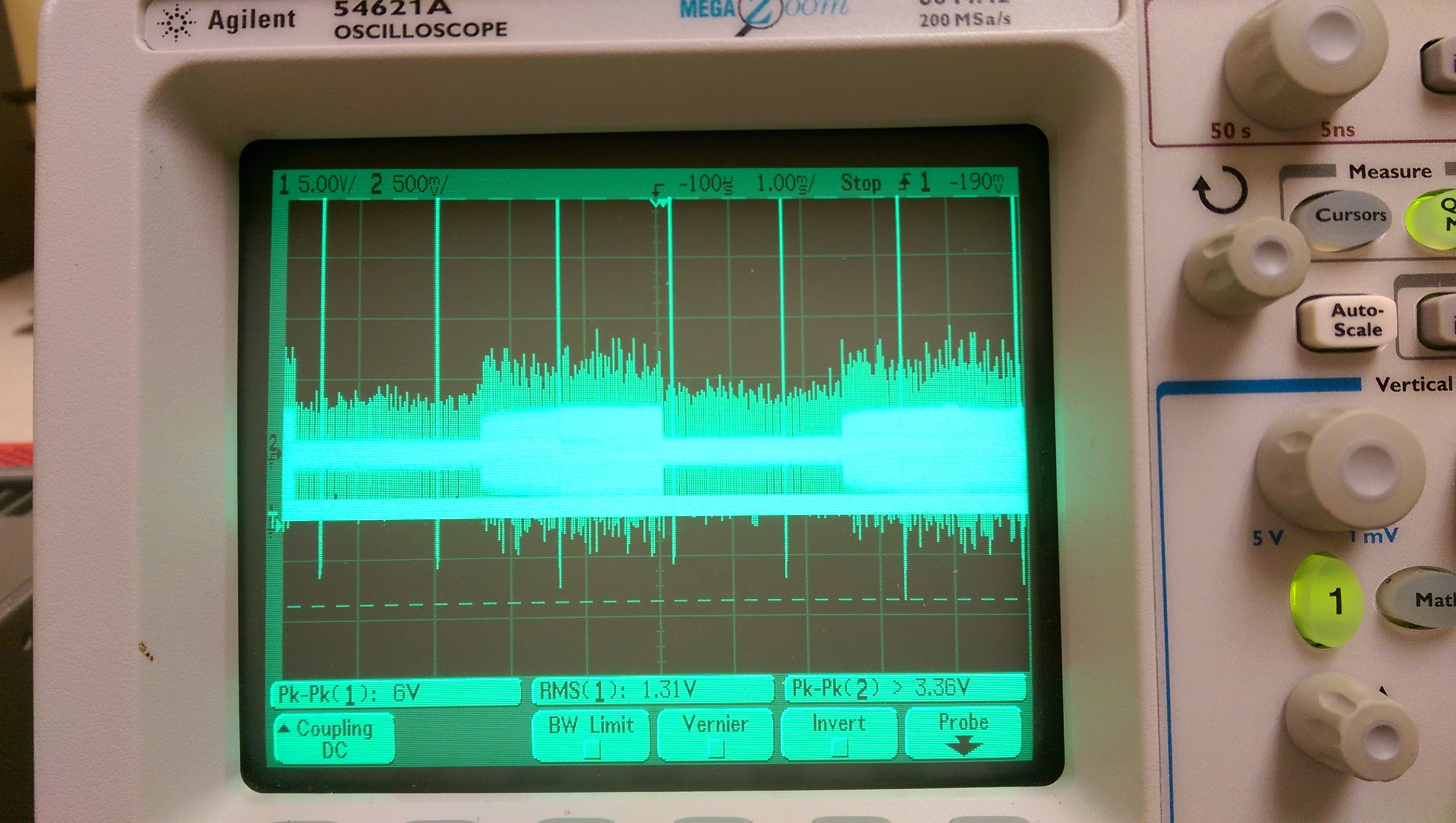
    Here is what I got with the A0- input tied to Vref at 2.5V. The first is a picture of just the clock source, the second is the clock and SDO. However, I believe there is considerable noise on the SDO signal at the scope. Not sure if this helps. Also, I have included a better graph of the output that I am getting.

    Thanks!

  • Sorry for the delay here Swanagan,
    Is that clock running at ~800Hz? Is this really coming from an SPI post or is this a bit banged routine? The SDO should not look lile that, it's way to noisy.