This thread has been locked.

If you have a related question, please click the "Ask a related question" button in the top right corner. The newly created question will be automatically linked to this question.

ADS7822 - no output data

Hi there.  

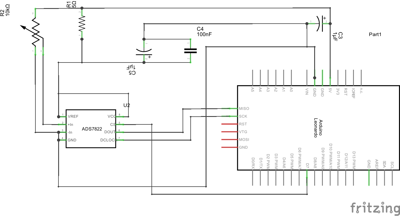
I have an Arduino Leonardo, I'm trying to talk with a TI ADS7822[1] . I've set up the application circuit per Figure 28 of the ADC spec sheet, with the exception that I'm using a 5V supply. I'm using the wiper of a pot as the input for now (eventually this will be connected to a PT100).

Codewise I'm using the Arduino SPI library, with the SPI settings

SPISettings(SPI_CLOCK_DIV16, MSBFIRST, SPI_MODE3)

and I'm fetching two bytes of data from the ADC. Here's the problem: The ADC isn't outputting any data. Looking with my scope, when I set the chip select pin low, the SPI clock from the Arduino starts, but the Dout of the ADC goes low and stays low. When the chip select goes high again, so does Dout.

I can verify that the clock is running at 1MHz with my scope, and the +In is a voltage above zero. 

Let me know if I can provide any more information. 

  • Hello Jarrett,

    Welcome to TI E2E community & thanks for choosing TI ADC.

    I will need schematic of your ADC section and a oscilloscope capture capture of 1 SPI frame triggered at falling edge of CS before I can comment on possible cause of failure.

    Please share this information.

    Thanks & Regards,
    Shridhar.
  • Hi Shridhar,

    Here's a schematic.

    and here's the snapshot from my logic analyser. Input 0 is the clock, input 1 is the ADC's Dout, and input 2 is the chip select.

    Do you need a scope output specifically or will a logic analyser do?

  • Hello Jarrett,

    Thanks for sharing the schematic & the logic analyzer data capture.

    The schematic looks okay. Please confirm the GND trace gets connected to GND plane on Arduino board.

    For the logic analyzer data,

    1. The DOUT is expected to be in high impedance state till 1.5CLK after 1st rising edge of clock once the chip select goes low.
    2. I expect DOUT to hold its state (in this case HIGH) which may be determined by pull up resistance some where (either in Arduino board or by logic analyzer) till 1.5 clock after first rising edge.
    3. DOUT appears to follow the clock in this time period. Please check other connections if there is a connection being established between Clock & DOUT pin.

    Please check if you can perform following tests.
    1. Introduce buffer for digital connections between ADC & controller if controller IO is also working on 5V supply.
    2. If not introduce a digital level shifter between the two devices.

    An oscilloscope capture with these changes should be helpful.

    Thanks & Regards,
    Shridhar.