This thread has been locked.

If you have a related question, please click the "Ask a related question" button in the top right corner. The newly created question will be automatically linked to this question.

ADS124S08 DRDY does not go low consistently

Other Parts Discussed in Thread: ADS124S08, ADS1248

Hello There,

I am using ASD124S08 EVM and attempting to read a single channel.

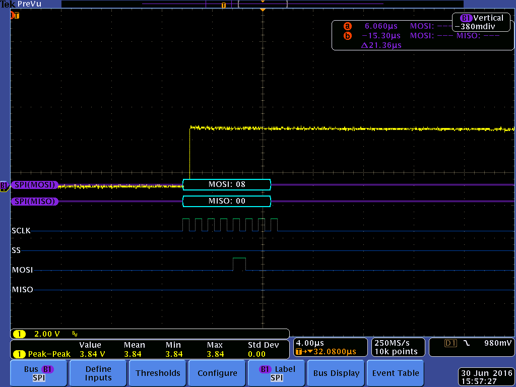
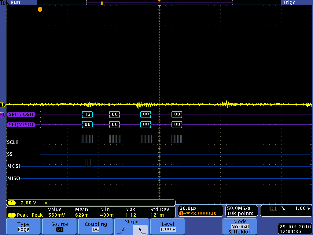
there is a stable SPI communication and I was able to read all register and verify the reset values.

I configured ANI2+ and ANI3-, with AN0 as the excitation source. the other setting are:

internal clock, and reference 2.5 always on. continuous conversion mode, 50SPS, excitation source 1 with 1000uA on ANI0.

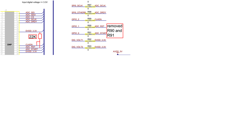
10Ohm resister is connected between AN2+,AN3-. AN0 shorted to AN2+ and ground shorted to AN3-.

with this, when I activate the channel, I can measure 10mV across the resistor. reference voltage of 2.5V is also observed.

the start pin is tight to 3.3V and I also send START command after configuring the channel.

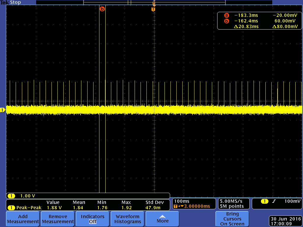
after the above setting, currently I read the channel every 300ms and monitoring DYDR signal. I expect the DYDR signal to toggle after each conversion. but this is not observed. the DYDR signal is always high.

is there a specific sequence for channel configuration?

do we have to toggle the START pin before every conversion?

I had observed the DYDR pin toggling when I was trying to connect the START to +3.3V. but it was not consistently working. with START pint tight to+3.3V the DYDR is always high.

can you please help me identify where I am going wrong.

thank you.


  • Hi Rupesh,

    First, make sure that you do not have contention between your connection to the START pin and the EVM trying to drive the START pin (remove R91).  If all supplies are active (DVDD/IOVDD/AVDD/AVSS) and the RESET pin and START pin are high, then you should see DRDY toggle at the specified data rate.  If you attempt to read from the device, the SCLK will drive the DRDY high.  If you toggle the START pin, the conversion will restart and DRDY will go/stay high.  If you issue the START command, then the conversion will start/restart.

    If you set the START pin high, then you only need to send the START command one time to start conversions.  If you do not read from the device you should see DRDY toggle at the specified data rate.  I would make sure that this is working before attempting further communication to the device.  As soon as you try to communicate the SCLK will drive the DRDY pin high.

    Can you send me logic analyzer/scope shots of the communication and DRDY?

    Thanks,

    Bob B

  • Hello Bob,

    thank you for the response.

    based on you reply, we removed the R91. and pulled up START and RESET bin using a 22k ohm resistor. we now observe a steady RESET and START signal. all the voltages are at expected levels. we also send a "START" command once at the start of conversion.

    but the DRDY signal is not observed toggling. please see attached for single shot conversion mode. same was observed when we configured in continuous conversion mode.

    the yellow trace is for the DRDY signal.

    the SPI bus timings are retained from ADS1248 for now. I will be updating it soon for ADS124S08

    Again, for a short duration we did see DRDY pulse at 60ms(we set 50SPS). but after power cycle, it did not work and we were able to read the data from the channel.


  • Hi Rupesh,

    First of all, could you be more specific as to how you connected the pullup resistors to START and RESET?  Maybe a picture of your setup would help.

    One thing that will be problematic is your SCLK should be dwelling low and not high.  Data should change on the rising edge of clock and be stable on falling edge.  Can you correct the SCLK and send me an updated scope shot of the START command, and then another shot of DRDY zoomed out?  Right now it appears that the device is not converting.  If START is tied high, then you are in continuous conversion mode after the START command has been issued.  The device will stay in continuous conversion until a STOP command is issued.

    Again I emphasize that to properly troubleshoot your issue that you do not try to achieve the end result by executing a lot of commands. Instead, take it one step at a time. Following power-up, I would write the register settings and then verify by reading them back.  Then I would issue the START command only.  Do not send any further commands or data reads. At this time you can monitor DRDY.  If DRDY toggles at the assigned data rate, then you can proceed forward.  Until you have verified that all your initial commands and pin connections are correct it is very difficult to follow what is happening to the device or your code.

    Best regards,

    Bob B

  • Hello Bob,

    thank you for your inputs and pointing out the mistakes.

    from the waveform it looks like DRDY is working now. I had performed the initial test like reading back configuration register after my first post. and they were fine. hence we started working on data read with timer (not using DRDY). as the data always read 0, we started monitoring the DRDY. it would have been good if we had started monitoring DRDY first as you suggested. thank you.


    connecting pull-up for RST and START:


    behavior of DRDY on start command:


    only monitoring DRDY toggling after START command at 50SPS.


  • Hi Rupesh,

    The screen shots look like what should be expected.  I think you may have incorrectly drawn the pull-up diagram (connections to CLK_EN and ADC_RST) but indeed have it correctly connected based on the scope shots (ADC_RST and ADC_START). 

    There is a slight difference in the voltage levels between the two scope plots.  The first plot looks to have an output of about 3V, but the second appears to have an output below 2V.  Maybe this is a connection issue with the probes.

    Are you now getting correct data?

    Best regards,

    Bob B