This thread has been locked.

If you have a related question, please click the "Ask a related question" button in the top right corner. The newly created question will be automatically linked to this question.

DAC084S085 outputs is always low !

Guru 20755 points
Other Parts Discussed in Thread: DAC084S085

Hello,

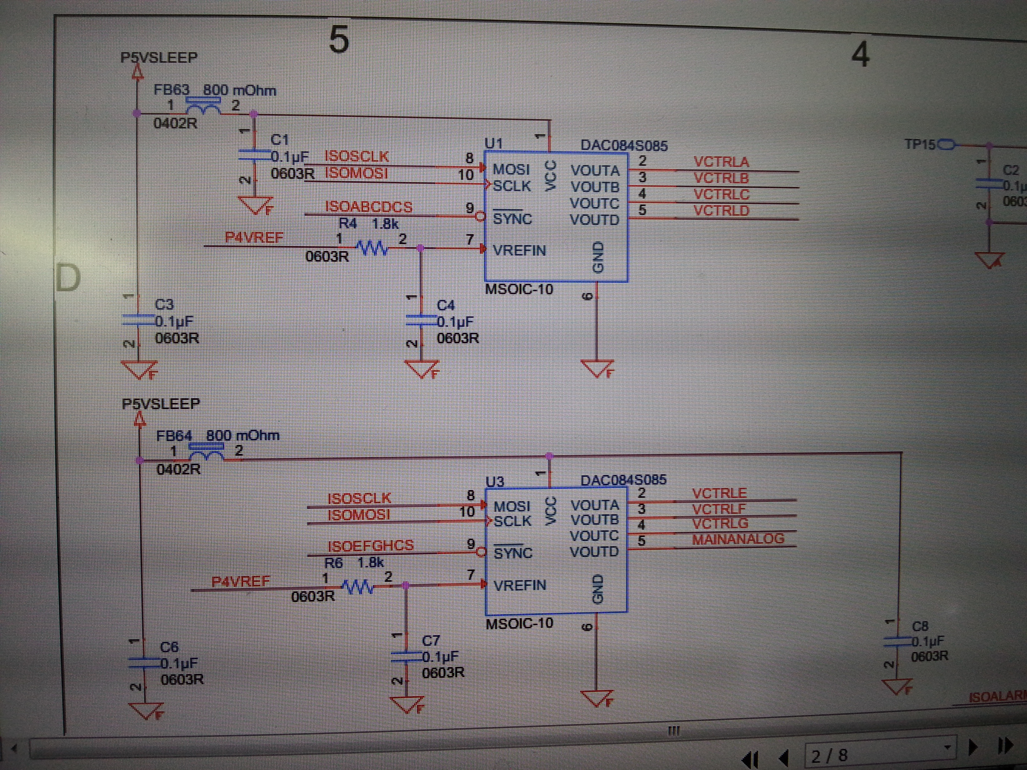
I have some troubles when trying to use DAC084S085  in board.

The output is always zero whatever I do.

I am writing spi register as advised in datasheet, but nothing helps, and the output keep being zero.
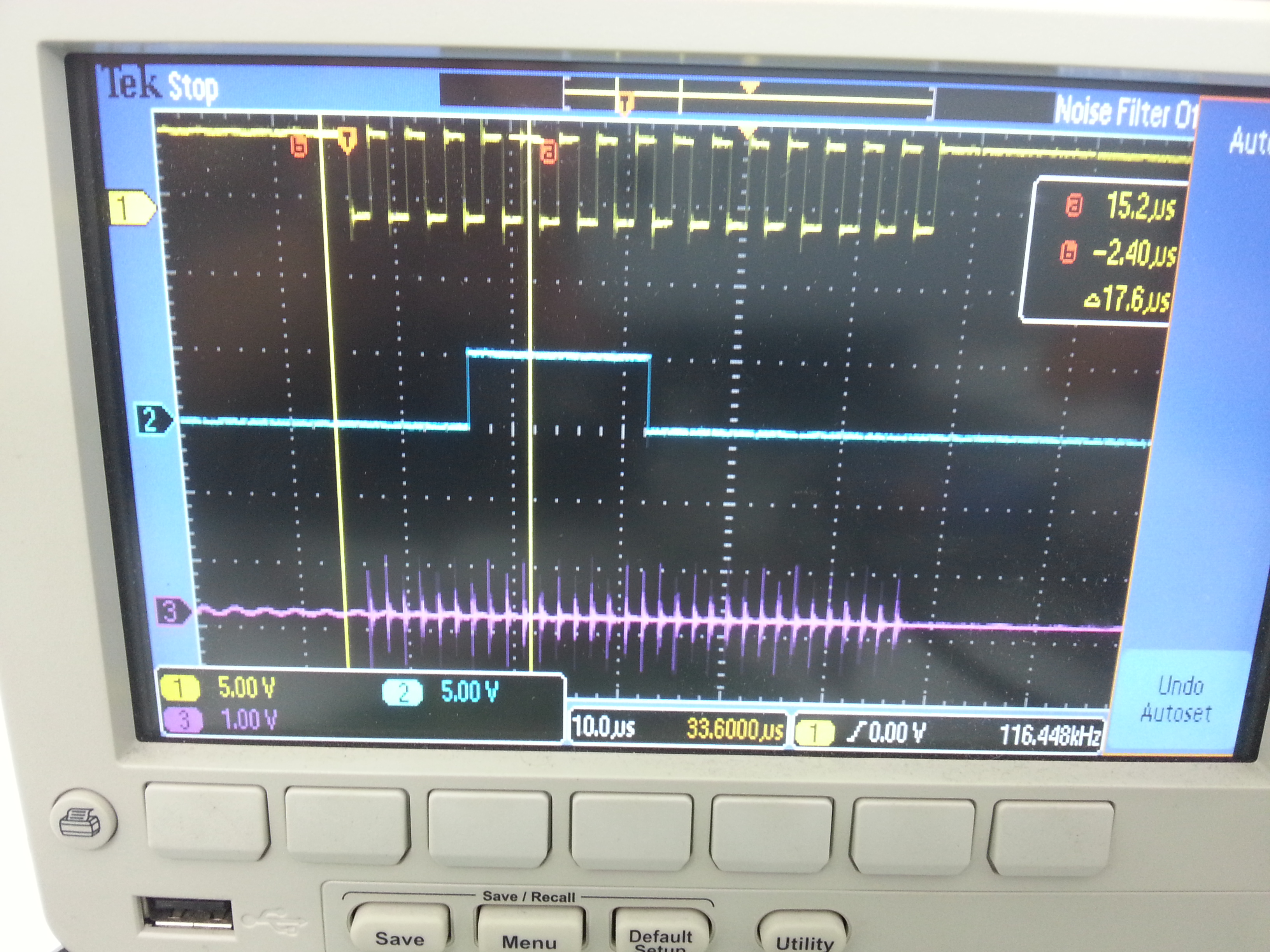
yellow - SCLK

blue - DATA

purple - output (voltage is zero)

Are there any suggestions ?

Best Regards,

Ran

  • Hi Ran,

    Some things to check:

    Do you have a SYNC signal that goes low before the first clock and then goes high after the last clock as shown in Figure 2 of the datasheet?

    Are all the SPI signals at the pins of the part?  This is to make sure that there is no discontinuity between the source of the SPI and the DAC.

    Check also that you have 5V at pin 1 and your reference voltage at Pin 7. 

    The purple trace is pin 2?  The data you are sending should change DACA which is pin 2.  Check also right at the pin. 

    Mike

  • Hi Michael,

    Thank you so much for the quick reply.

    Please check my answers here:

    > "Do you have a SYNC signal that goes low before the first clock and then goes high after the last clock as shown in Figure 2 of the datasheet?"

    Yes, CS is not shown in the attached image, but CS goes from high to low, before the clock starts. All clocks cycles(16) are inside the CS low region.

    > "Are all the SPI signals at the pins of the part?  This is to make sure that there is no discontinuity between the source of the SPI and the DAC."

    I think so, please see shematic below (it contains 2 DACs on board - none of them works yet)

    >"Check also that you have 5V at pin 1 and your reference voltage at Pin 7. "

    As you can see in the below scematic, both pins are connected.

    >"The purple trace is pin 2?  The data you are sending should change DACA which is pin 2.  Check also right at the pin. "

    Yes, but it is always zero (yet, it has a lot of noise).

    How can I be sure that this device is alive in any way if it is always outputs zero with noise ? Mayve I can read registers ot tell the device to start with "1" in all outputs ? 

    Thank you very much!

    Ran

  • Hi Ran,

    Looking at the schematic, it looks like the SCLK and Din signals are switched. Pin 8 is Din (MOSI) but the trace that connects to it is ISOSCLK. Pin 10 is SCLK and the trace connected to it is ISOMOSI.

    Mike
  • Mike,

    That's great. It works now.
    The mistake skipped our eyes.........

    Regards,
    Ran