This thread has been locked.

If you have a related question, please click the "Ask a related question" button in the top right corner. The newly created question will be automatically linked to this question.

How to provide CONVST (Conversation Start) using SPI DMA to ADS7863

Other Parts Discussed in Thread: ADS7863, OMAP-L137, ADS8361, ADS7861

We are using ADS7863 in pseudo differential mode I i.e. 3 x 2 non differential signals are output to SDOA, SDOB. We need to get the Data in the DMA mode?

Question: How do we drive the CONVST (Conversation Start), RD and CSbar pins?

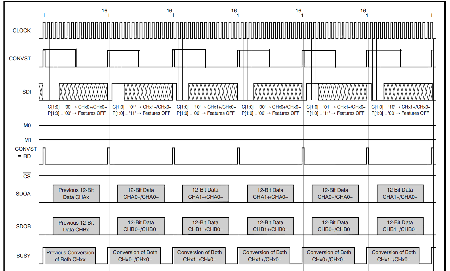
The application note suggests connecting CONVST to RD and CSbar to GND. If this is good, then how do we drive CONVST line? Can we use CS of the master SPI (since the CS is grounded)?

Any suggestions are appreciated.

  • Hi again Sanjay,

    If I remember correctly, you are connecting the ADS7863 to the OMAP-L137.  I'm not sure how well this will work using DMA, but the ADS7863 needs an active high signal applied to both the RD and CONVST inputs.  There are several application notes on the web for the ADS7861 and ADS8361 that describe how to manipulate the combined RD+CONVST (i.e. tie the two inputs together) using an SPI port. Go to the product folders for either the ADS7861 or the ADS8361 and click on the Application Notes link which is to the right of the 'Most Popular Links' box.

    You could use the slave /CS from the OMAP-L137 to drive chip select on the ADS7863, or you could simply ground that input.  For the combined RD+CONVST you could use a GPIO, but that may have issues working with the DMA controller.  Another option might be using the timer to generate the RD+CONVST input, perhaps in conjunction with the GPIOs.

  • We could not find a document to drive RD+CONVST using an SPI port - that would be an ideal solution for us. We found an example driven by McBSP. This does not work for us since we need to drive two SPIs simultaneously using a DMA.

    Do you think that we can get the DAC data connecting RD+CONVST to /CS?

    Another method may be is to use a Frequency divider of 8 i.e. "CONVST =  Clock/8" (see modified CONVST below). Nothing has been mentioned about the falling edge of CONVST hence CONVST = CLOCK/8 should work. Please provide your thoughts.


    Regards,

    Sanjay 613-355-9298


  • Sanjay,

    RD+CONVST must see a clock edge while they are active (high) so you cannot use /CS directly.  Using the modified CONVST should work.  Since you are using two SPI ports on your processor, one as master the other slave, you can look into using the slave transmit of port 2 (MISO) to drive the combined RD+CONVST by writing perhaps 0xFF00.

  • Tom,

    Seems following is the suggestion.


    0x8000 should perform the same as 0xFF00. Do you foresee any issues?

  • Potentially there is an issue with 0x8000 as the input  - note on page 7 of the data sheet that the RD input uses a falling SCLK edge to qualify the read signal, while on page 8 the CONVST wants to see a rising edge.  You should plan on writing (at least) 0xC000 so that the 'pulse' on the RD+CONVST is two clocks wide.