This thread has been locked.

If you have a related question, please click the "Ask a related question" button in the top right corner. The newly created question will be automatically linked to this question.

ADC08200: ADC output data

Part Number: ADC08200

Dear all,

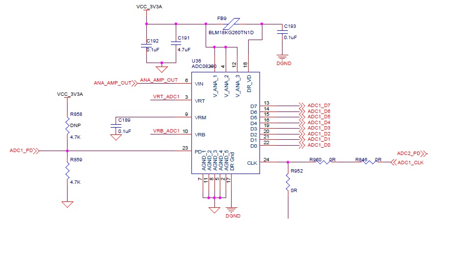
I am using ADC08200 in one of my project. I am giving the input data with 1KHz pulse and I am giving the samples clock 20 MHz and tried with 50MHz also. i am getting ADC out constantly FF. The output of the ADC is not varying. Could you please give me the solution. Here i am attaching the schematic. R952 we are using provision to give clock from externally.

Thanks & Regards,

C Ashok Reddy

  • Hello

    I have a few questions about the schematic details.

    1) What are the DC voltages on VRT_ADC1, VRB_ADC1 , VRM and ANA_AMP_OUT when the pulse is active and when it is stopped?

    2) What is the bottom end of R952 connected to?

    3) How are the AGND and DGND netws connected? I don't see a connection point on this schematic. The connection should be near or under the ADC.

    4) Have you confirmed the power supply voltages at V_ANA and DR_VD are within the required range per the device datasheet?

    Best regards,

    Jim B

  • Hi,

    1) What are the DC voltages on VRT_ADC1, VRB_ADC1 , VRM and ANA_AMP_OUT when the pulse is active and when it is stopped?

    VRT_ADC1: 2.1V  VRB_ADC1= 400mV  VRM=1.36V  ANA_AMP_OUT=3.44V

    2) What is the bottom end of R952 connected to?

    Ans: This we are using as a provision to give clock input from externally.

    3) How are the AGND and DGND nets connected? I don't see a connection point on this schematic. The connection should be near or under the ADC.

    Ans: We shorted these two nets near the power supplies of ADC.

    4) Have you confirmed the power supply voltages at V_ANA and DR_VD are within the required range per the device datasheet?

    Ans: These supplies are connected asper the datasheet.

    Thanks & Regards,

    C Ashok Reddy

  • Hi Ashok

    As discussed in the PIN DESCRIPTION AND EQUIVALENT CIRCUITS and Operating Ratings tables, and the REFERENCE INPUTs section of the ADC08200 datasheet, the VIN voltage should be less than Vrt and greater than Vrb.

    In your case the VIN level is 3.44V, while Vrt is only 2.1V. That is why the converted output is FFh.

    You will need to reduce the voltage of ANA_AMP_OUT to below Vrt, or increase the voltage of Vrt.

    Best regards,

    Jim B