Because of the holidays, TI E2E™ design support forum responses will be delayed from Dec. 25 through Jan. 2. Thank you for your patience.

This thread has been locked.

If you have a related question, please click the "Ask a related question" button in the top right corner. The newly created question will be automatically linked to this question.

ADS1115: Half-blown inputs with major crosstalk, but don't know what went wrong!

Part Number: ADS1115

I hope this is a viable question, but I have an issue with a circuit involving two ADS1115 modules, and eight MAX4080SASA high-side current sensors.  (All purchased from eBay, as I can't hand-solder the ADS1115 chips.)  Basically, I am trying to use the MAX4080S chips to measure the current draw through a number of DC breakers on a 48v DC system; the ADS1115 modules convert the output of the MAX4080S chips to digital for the microprocessor.  The MAX4080S chips handle up to 80v differential on the current sense inputs, which means that they should be just fine in the event that a breaker trips (expecting maxed-out readings).  In this case, I have a 100A 1-milliohm "main" DC breaker between a 48v battery bank and a 3KW DC inverter; I also have five 10A DC breakers (14 milliohms apiece) connected from the inverter's DC lugs to smaller DC loads.

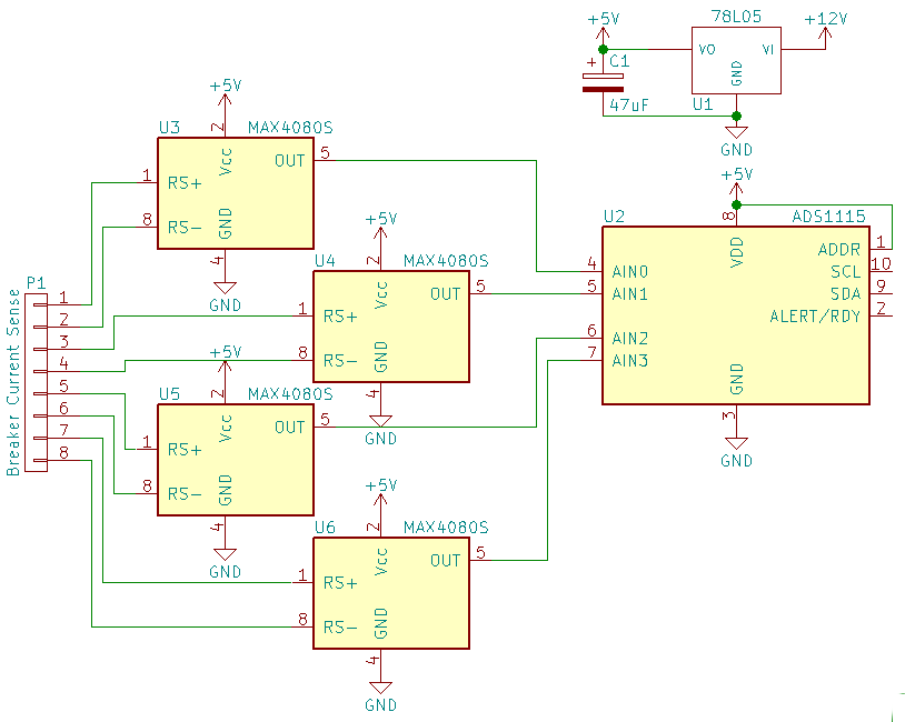
Works great in theory...here's a KiCAD schematic of 1/2 of the circuit (the other half being exactly the same, except that "ADDR" on the ADS1115 goes to GND; they share the same I2C bus.

I actually had it working pretty good on 5 smaller breakers, using 22K resistors in series with both leads of the the MAX4080S chips to scale the range.  ADS1115 resolution was near 1mA, which was very good.  I could almost taste completion of the project...

When I connected the sense wires from the main 100A system breaker to a MAX4080, I got a nice reading.  But when I increased the load to approximately 40A for a test (plugged a 1500W space heater into the breaker), the MAX4080 blew out (VCC/5v rail shorted down to 1.65v).  The MAX4080 chips are rated for 80vDC on both the current sense leads AND VCC...and I only had 51v on the system.  I have no idea what happened, and it's extremely unlikely that there would be 30v transients induced in 4 feet of coax cable (my current sense wire between the breaker terminals and the MAX4080).  Anyway, I removed the blown MAX4080 module (restoring functionality in reading the already-connected 5 breakers), and tried the next MAX4080S module in line.   This time, I soldered a 0.1uF/100v capacitor across the MAX4080 sense leads (transients??), as well as some 4.7K scaling resistors in series with the sense wires.  Time for a second test...but this time, both ADS1115 modules (!) immediately malfunctioned when I connected the sense leads to the MAX4080!  They only outputted different but static values for each channel--despite multiple resets (unplugging and shorting power supply capacitor out, I2C master reset command, etc.), they always returned exactly the same values. 

I spent several hours debugging and revamping my I2C routine (had issues with "wait-for-conversion" lockups if the ADS1115 got reset!), and somewhere in there the ADS1115s' static values started changing.  It seems they are working a little better now, but are still completely unusable.  Anyway, I was able to confirm the following:

  • the ADS1115s are responding to the I2C commands perfectly, and don't respond if given an invalid I2C address
  • after the one-shot conversion is started, the ADC conversion flag is going from 0 -> 1 like it's supposed to
  • crosstalk between the channels is at completely unusable levels

The outputs of the MAX4080S modules seem to be working fine, with voltages right around where I'd expect for the input loads (I'll check further)...but nothing close to what the ADS1115s are reporting via I2C.  I'm not doubting that the ADS1115s are damaged, but my question is: HOW am I blowing things up with this?  What in the world is going on?  With an 80vDC limit, I would expect the MAX4080S chips to be virtually indestructible.  Yes, there's the -0.3v absolute minimum on the sense leads, but with the sense leads up at 50vDC...???  Perhaps voltage is getting induced into the 78L05 (or backfeeding through a MAX4080) and bumping the output voltage beyond the 7v absolute max. of the ADS1115s?  (Remember, both ADS1115s simultaneously quit functioning.)

I'm completely baffled.  Any engineers with a clue? 

(02-26-17, 6:57 PM EST...corrected some typos, made clarifications, etc.)

  • Hello Sid,

    Thank you for your query. Someone will get back to you during the work hours.

    Regards,

    Krunal

  • Sid,


    There's nothing in the ADS1115 that would make it any more or less susceptible to damage from an overvoltage event. In the ADS1115 datasheet, there is a table for Absolute Maximum Ratings on page 5 of the datasheet. It would appear that somehow you've blown past those ratings on the inputs of the device.

    I'm not sure exactly how your system damaged your device. I'd need to know more about the entire system and how it's set up.

    I will say that tripping a breaker might spike voltages to a very high level. At one point, I'd worked on hot swaps for server components, and without some sort of TVS on the input side of the pass transistor (breaker for your case) you could easily double the input voltage for a very short duration. On the output side of the breaker, you'd still need a power Schottky to ground to prevent the supply from going several volts below ground. It all depends on the amount of inductance on the supply line. It doesn't take much to be destructive.

    If you have one, you might want to check out what happens on either side of the breaker with an oscilloscope. You would need something fast enough to record a spike that is short in duration. However, I think that a 500MHz would be the minimum bandwidth required for the scope.


    Joseph Wu
  •   Thanks for the suggestions.  I agree that somehow some rating was exceeded...I'm just not sure which one!  I'm aware that turning a breaker off could result in some sort of inductive spike below the rail (on the LOAD side of the breaker)--but I didn't have anything blow out when I was turning breakers on and off.  It only happened when I increased the load on the inverter.  That's what I don't understand.  (BTW I never turned the main 100A breaker off with the circuit connected.)

       I do have a scope...a 20MHz tube-based analog 'scope!  Not quite sufficient for watching transients.  Attached is an updated KiCAD schematic, showing the connections...

       Yes, the "GNDs" are all the same.  B1-3 are the DC load circuits.  Not shown is the 48v -> 12v converter connected to "b2" to power the circuit and several other devices.  Strangely, the only MAX4080S that blew was the top one (U3)...after swapping for a different MAX4080S board and adding the 4.7K resistors, that's when both ADS1115s (U2 and not shown) quit behaving properly.  If one or more MAX4080S chips shunted a transient to VCC, I think that would blow the whole ADS1115, not just the inputs.  But they didn't seem to like 50v across the "RSense" leads when I turned a breaker off: the output would slowly "float" to 5v over three or four seconds...despite being rated for a max of 80vDC across RSense.

       I have ordered a pack of a hundred UF4004s for a different project...would a dozen of those work to prevent negative transients?  They do seem to have a rather high forward voltage (between 0.6 - 1.6v) when compared to the -0.3v absolute maximum of the MAX4080, though.  Other quick ideas: there's also the 100v 5A SR5100 (0.4-1.4v, not much better than the UF4004!), and a 100v 0.1A BAT41 (0.2-1.2v, but MUCH lower current rating!)
       I've also considered a UF4004 on the current sense circuit's GND to "float" the whole circuit up 0.6v or so in order to properly shunt negative transients with UF4004s to the true GND.  Or maybe a dozen capacitors (from each RSense lead to GND) to try to absorb the transient?

       BUT...(correct me if I'm wrong) it seems to me that a transient would have to be able to dissipate some current to do damage.  The 10A breakers all have 22K in series (required for scaling), but that requires 440vDC to get 20mA current to flow!  However, it only requires 94vDC to get 20mA through the 4.7Ks on the 100A breaker.  (Still well within the range of a 100mA BAT41 @ 0.2vDC.)

      Some design clarifications: the "current sense" wires from the 100A breaker are a 4-foot coax cable (shield = load, "wire" = battery, for a little safety!)  The current sense board is mounted directly to the enclosure for the (5) 10A breakers, so the (twisted) current sense wires are all of six inches long.  The 100A breaker is bolted directly to a plate of steel that is mounted to the battery terminals; it is the main system disconnect (rated 10,000AIC).  Let me know if there's something more I need to describe. 

  • Sid,


    I'm not sure I'm going to be able to help on this one. I don't think the problem is with the data converter, but rather some sort of over-voltage in your system.

    Your application is similar to a solar inverter type of application. In similar designs that I've seen, people use some sort of galvanic isolation or magnetic sensor to isolate one side from the other (precisely because of possible over-voltage events). However, I'm not familiar enough with those designs to be of much help. There are various TI designs and application notes that are available that might help you with a different method of current measurement.

    If you do stick it out with this design, one thing to try would be gradually increase your inverter load to see if any of your DC voltages rise (either +12V or +5V supplies, or any analog inputs). Additionally, I'm not familiar with MAX4080S enough to help out. You may want to contact Maxim to see if they have any problems with the output spiking with high voltage inputs.

    IF you do decide to insert some protection diodes, I've seen the B380 diode used for a 48V system to prevent the supply from going below ground in a 48V hot-swap application. The B380 is little better than the UF4004 in forward voltage, and it will take more current continuously and in short duration.

    For the supply voltage going high, I think the Littelfuse 5.0SMDJ series is good. If you are having over voltage events, you could use the 5.0SMDJ54A for the 48V supply. Also, you might want to protect your 12V supply as well with a 5.0SMDJ12A.


    Joseph Wu