This thread has been locked.

If you have a related question, please click the "Ask a related question" button in the top right corner. The newly created question will be automatically linked to this question.

DAC60004: Issue with DAC output

Part Number: DAC60004
Other Parts Discussed in Thread: TMS320F28335

Hi

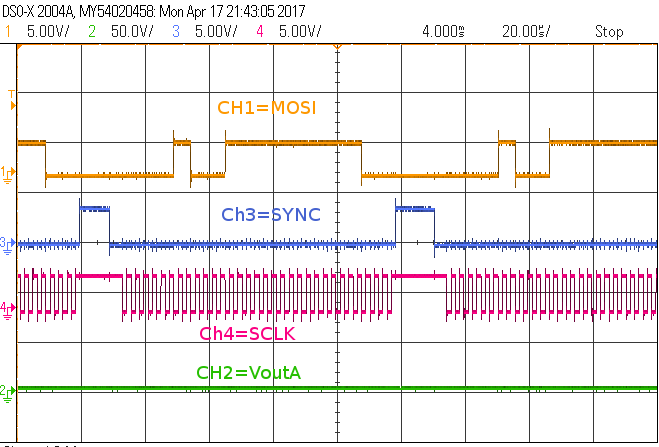
I have been trying to use DAC60004 with SPI communication using TMS320F28335. The SPI part of the code is working well. But the DAC output is always zero. I have tied LDAC(pin1) to zero and CLR (pin9) to VDD. The REFIN(pin7) and POR(pin6) are both connected to VDD (pin3). SCLK from dsp to pin 14 and MOSI from dsp to pin 13. The SPISTEA signal of dsp is used as SYNC (pin 2).  The command given is 0x030FFFF0h- (command-write to buffer and update DAC n/ Channel A/DAC data FFFF). The SPI inputs to the IC is captured and attached with. I have a doubt regarding the dac data to be send. Though the DAC60004 is 12 bit, I suppose if FFFF is send from MOSI, the DAC should ignore the bits from D07-D04, so that the mode bits is always from D03-D00. Correct me if I am wrong. Also Is there a mistake in tying the LDAC to GND  with the command given as write to buffer and update DAC n (D27-D24=3)? Could anyone help me out with this?

Regards

Deepthi


  • Hi Deepti,

    Thanks for your query. Your configuration looks fine to me unless you are doing something extra that is not listed. You should be able to see the output. The only thing I can notice is that the scale for VOUT on the scope is 50V while all others are at 5V. I don't know whether it was done intentionally or not. If this is the reason, then great or else could you try checking on another device or EVM, if you have with you?

    Regards,
    Uttam Sahu
    Applications Engineer, Precision DACs
  • Hi Uttam,

    Thanks for the reply. The scale on the graph was accidentally made 50V per division. But I was checking the average value of the corresponding channel on the scope which was reading as  few mV only. I changed the scale and took results again but the result is still the same i.e Vout for channel A is always near to zero. I was checking with a discrete breakout board for TSSOP-14 package, not the EVM. I already tested with 3 DAC60004 ICs. I am not sure if its a problem with the IC lot that I got. I guess that case is rare. Do we have to make the CLR pin have a high to low transition after every transmission operation? Just like an inverse of SYNC pulse? Or can it be made always high?

  • Hi Deepti,

    The problem looks strange. I don't think there should be problem with all 3 devices. The CLR pin doesn't need to have transition. It can be help HIGH all the time. Can you please share the schematics of the board? Please note that it is a public forum. If you don't want to share the schematics you can send it to my mail. Please let me know if that is ok.

    By the way, can you make your SCLK INACTIVE-LOW and try?

    Regards,
    Uttam
  • Hi Uttam,

    Since I am testing the DAC portion separately, I can share the schematics which is attached along with. I tested with SCLK INACTIVE-Low, the outputs are tied to the power on reset values. If I keep POR connected to VDD then the ouputs are at mid scale else if POR is grounded then the outputs are at zero scale even when the code is running. After checking with inactive SCLK, I tested again with the active clock. I get the same results. Maybe I should order and get an EVM and try with it.

     dacboard.pdf

  • Hi Deepti,

    I am sorry for the delay in response. The schematics you sent is very basic and doesn't provide enough information. Could you please share the output circuit? You can try it on an EVM if you have already got one to isolate the problem. As the problem seems very basic, I will need more information on the settings and interfaces. Sorry for not being able to provide a straight forward answer but the configuration seems too simplistic not to work unless there is some very basic issue. You can try a few things as below:

    1. Try writing and reading back few registers to confirm that the SPI communication is not a problem
    2. Try monitoring the power down bit to confirm the device is not in power down
    3. Try setting the mid code and check output
    4. Check the reference voltage
    5. Check whether the output stage can load the device and if possible, isolate the output
    6. Monitor supply current when you write different codes - you can know whether the device is in power down, normal mode or short-circuit mode from this current value

    Regards,
    Uttam