Captured to Crystal Startup Issues wiki page

This thread has been locked.

If you have a related question, please click the "Ask a related question" button in the top right corner. The newly created question will be automatically linked to this question.

ADS1258: No /DRDY pulses (Crystal Startup Issue)

Part Number: ADS1258

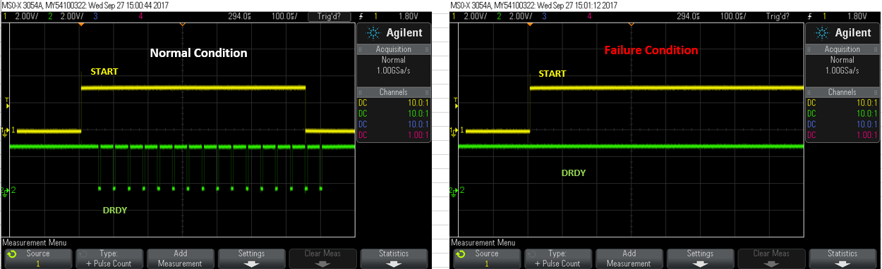
I have one pc of ADS1258 which always output incorrect value. After checking, I found that the data is always not ready after pulling START pin high.

What hardware failure could have cause the data output always not ready as the FW control is the same (same MCU). Thanks.

  • Hi Joes,

    Some reasons why you might not see /DRDY pulsing would be...

    • The device is not properly powered or the device is being held in power down (/PWDN = low). 

    • There is no ADC clock (external clock is not enabled or crystal is not oscillating) or the CLKSEL pin in configured incorrectly.

    • The device is being held in reset (/RESET = low).
    • The device has been damaged by electrical overstress.

    I would start by double checking the power supply voltages, the state of the GPIO control pins, and whether or not the clock is active. I would suggest triggering off of the /DRDY signal (if you're not already), just to be sure that a slow data rate or power supply ramp up isn't causing the /DRDY pulse to occur off screen.

    If those all look okay, then I might recommend getting a few more sample parts and replacing the ADS1258 to see if perhaps the device was somehow damaged.

    ...My guess would be that there is either a GPIO pin setting that was simply overlooked or that the ADC clock is missing.

    I hope that helps,
    Chris

  • Hi Chris,

    The oscillator won't oscillate unless I place my probe on it (XTAL1 or XTAL2).

    It seems like I have to increase the capacitance value as my probe capacitance is 11pF.

    But the oscillator type (MC-306 32.7680K-A0) and capacitor chosen based on recommended part and value in ADS1258 data sheet.

    Can you advice what could have turn wrong for this particular case as I don't see any issue in other boards.

    Thanks.

  • Hi Joes,

    There are a lot of variables and circuit tolerances that might affect this circuit and prevent it from oscillating...

    1. For one, make sure the PCB has been thoroughly cleaned and check for any visible solder flux residue which adds parasitic impedance and may prevent oscillation.

    2. The load capacitors and parasitic PCB capacitors may vary, and so from board-to-board you may see some differences. A good practice (you're currently using) is to use C0G-type capacitors, which have a lower temperature coefficient, and so will be more stable over temperature.

    3. The crystal load capacitance is actually the series combination of the 4.7pF capacitors (4.7pF // 4.7pf => 2.35 pF load). This may be fine for some crystals, or in cases where the parasitic PCB capacitance accounts for the missing 10 pF. I might suggest increasing these capacitors to see if that resolves the issue. Some other E2E threads have reported success with increasing these capacitors to 22 pF.

      1. NOTE: I believe the 4.7 pF capacitor recommendation was a result of testing and optimizing this circuit with the Epson C-001R recommended crystal. These capacitor values may not apply to the other recommended crystals which were added to the datasheet later on.

    4. Another thing I've recently found has helped someone else with a similar issue was to add a 1-10 MOhm resistor in parallel with the crystal. Such a resistors exists inside the ADS1258 but with a fair amount of tolerance. Adding this resistor may help to reduce that tolerance and provide a more consistent DC bias.

    Best regards,
    Chris

  • Hi Chris,

    I try to add 10pF parallel with 4.7pF and the ADS1258 is working.

    However, I wonder why ADS1258 datasheet recommended for 4.7pF capacitor value for a 12.5pF CL crystal?

    Is it because by assuming PCA stray capacitance to be 10pF or there is capacitance across XTAL1 and XTAL2 internally of ADS1258?

    Thanks.

  • Hi Joes,

    I glad you've gotten the circuit working.

    I'm not exactly sure why 4.7pF was recommended, it very well could be assuming that parasitic capacitance would make up the difference. However, keep in mind that recommendation was for a specific crystal type.

    In general, smaller load capacitors usual supply more power across the crystal which can increase the oscillation amplitude and reduce the crystal's start-up time. However, depending on the crystal's particular characteristics, the smaller load capacitors may not be providing sufficient phase delay to cause the internal amplifier to oscillate.

    Best regards,
    Chris

  • Hi Chris,

    Noted, thanks for your support and explanation.