This thread has been locked.

If you have a related question, please click the "Ask a related question" button in the top right corner. The newly created question will be automatically linked to this question.

AMC7834: AMC7834 Vssa clamp supply sequencing issue

Part Number: AMC7834
Other Parts Discussed in Thread: TPS7A33,

Hi,

I have a problem with my MMIC bias circuit using an AMC7834 for the analogue parts.

The problem is around the negative supply rail and the Avss clamp function of the bipolar DACs in the AMC7834. If the negative supply is not present, the negative rail seems to be internally pulled up to about +0.4V (internal clamp diode?), taking the output of the bipolar DACs with it through the Avss clamp function. As my intended MMICs are very sensitive, this is not acceptable.

Please see the measurement below for clarification:

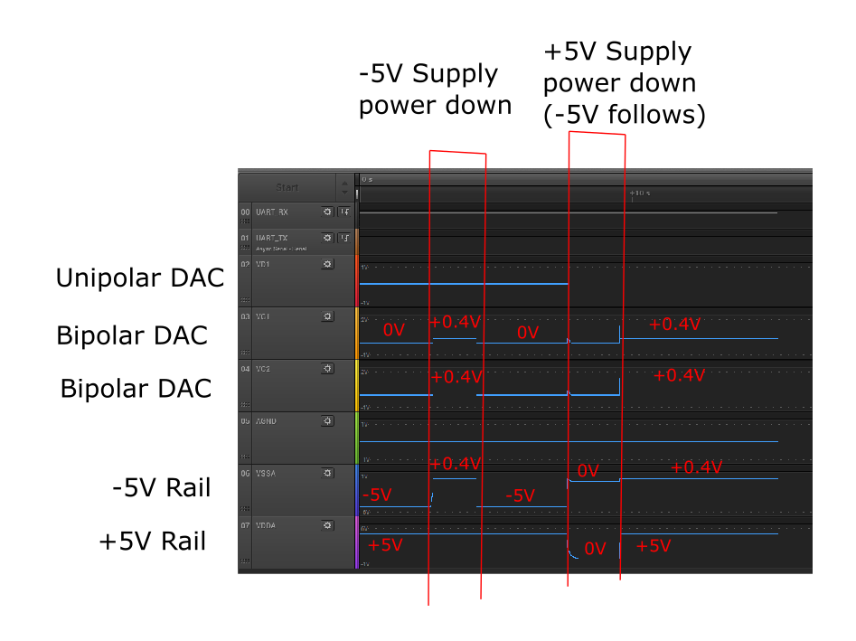
Now, I guess this is somewhat predicted behavior with the bipolar DACs, which only clamp to the clamp pin voltage (connected to Gnd) if the device is operating with all bias rails active, and otherwise to AVSS as far as I understand it.

The datasheet states that no specific power supply sequencing is required, however it looks like that the pull up to +0.4V is mainly due to the AMC itself - there's no external circuitry on the VSS rail, except for the LDO (ADP7182, weak 220kOhm pull to GND when powered down).

I have tried different things to bypass this - activating clamp manually (trying to force using the clamp pin voltage rather than AVss clamp) rather than relying on the AVSS alarm (with the Avss clamp), a simple pulldown to Gnd but it doesn't help the situation.

The only option I see right now to prevent this is to use a relais or equivalent transistor circuit to force AVss to ground if the external supply is not operating. As this requires a hardware change I'd be interested in other options, is there anything I haven't seen yet? Is this ~0.4V pull up standard for the AMC7834?

A different option would be to use a negative regulator which clamps the output strongly to ground when deactivated. The TPS7A33 used in the AMC7834EVM doesn't seem to do that either, so I'd expect the EVM to show a similar behaviour to my board. I have tested a 500 Ohm resistor between VSS and ground, that doesn't help the situation. Having a GND clamp option for the bipolar DACs would be great...the AVSS clamp seems problematic.

My AMC7834 is a version id 0 chip - bought recently from a major retailer. Could this be part of the problem?
The changelog in the datasheet doesn't seem to indicate so...

The AMC configuration is: bipolar DAC range 0-+5V, PA on, clamp deactivated (both tested), AVss alarm activated (both tested), open loop operation. DAC values set to 0.

Thanks,

Kai

*edit* to re-insert image that was missing.

  • Hello Kai,

    If you look at figure 45 from the AMC7834 datasheet, you can see the architecture of the bipolar DAC/clamp functionality.

    The DAC's output buffer is supplied by AVSS, so if the supply collapses (or becomes a high impedance path to GND) you will experience headroom issue when driving the output to GND.  If the buffer is sinking current you will see the voltage increase as there will be a voltage drop across AVSS to GND and the clamp resistor.

    Are you experimenting with supply collapse behavior? Or are you trying to implement a feature where your MCU disables the AVSS LDO for some kind of protection?

    I do not know of a simple configuration solution that would not require the modification of the design if you suspect that AVSS will always collapse first.  On thought would be implement a switch (like you mentioned), possibly controlled by a voltage supervisor.  

    Thanks!

    Paul

  • Hi,

    Thanks for your answer. My concern is both supply collapse and a unknown power up and power down sequence.

    I have just modified my PCB to also control the +5V LDO using the microcontroller, in the hope of reducing the issue by powering both +/- 5V rails on simultaneously. It does seem to do that, however, I still get an unavoidable negative pulse.

    It seems that whatever the sequence is that the bipolar DACs give a ~-0.8V pulse while the negative supply is ramping down to -5 V. I presume that is unavoidable as well and part of the AMC control logic? I would assume this is visible on the EVM as well?

    The slow start of my -5V LDO doesn't help, but I guess a faster turn-on would just yield a shorter pulse.

    It seems that adding some either relays or similar to short to the bipolar DAC outputs is the only way to create a spike-free output when using a negative supply. Is that the right conclusion?

    Is that the same on the EVM or is this a problem with my design?

    Thanks,
    Kai

  • Hi Kai,

    The DAC outputs will follow AVSS during power on until there is enough of a supply for the analog circuitry to take over. This behavior would be seen on the EVM as well. One thought is that you could use a analog switch /FET to connect AVSS to GND before the AVSS LDO is enable, allowing AVCC to turn on completely, then enable the AVSS rail and disable the GND connection. This would allow the DAC to be active in a unipolar supply condition. Another thought would be add a low pass RC on the DAC output, which may attenuate the glitch to some extent.

    Please let me know if you have more questions about this,
    Thanks!
    Paul