A related question is a question created from another question. When the related question is created, it will be automatically linked to the original question.
If you have a related question, please click the "Ask a related question" button in the top right corner. The newly created question will be automatically linked to this question.
I've never seen this behavior before in the ADS1000. How often does this occur for the read? Has the customer tried other devices? Is the data correct? In the scope photo, it looks like SDA is active with a pulse before SCL is given the start. Does this occur if SDA is not toggled before the SCL?
I'd like to see a close-up of the same problem. If they can get a clearer shot of this communication? Also, are they able to read back the register with extra SCL clocks?
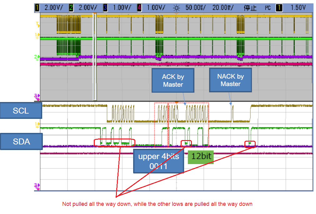
There is one thing that looks unusual in their photo. It looks like there are two different pull-down levels for this communication, where one is not pulled all the way down. I've circled those points in the plot:
Are there any other I2C devices on the bus that may have some sort of bus contention?
Thanks, you're correct. I can see the separate master and slave pull-downs. One other thing to check would be to duplicate Figure 7 of the datasheet with the optional readback of the configuration register. I want to make sure the configuration register is properly set.
Generally, the communications looks correct. Even with the SDA toggled before the SCL goes low, this should work. I just thought I'd check if removing the stop/start before the first communication would do anything.
I assume that the blue line in the plot is the power. When you describe this problem, you say that it occurs 3 out of 20 times. Does this problem occur only at start-up? or is it during any later reads?
In my previous post, I was asking for the configuration register. I wanted the customer to read back the register by adding in another byte of SCLKs. There are two things that I wanted to see. First, I wanted to make sure that bit 7 is a 0. With ST/BSY as a 0, it means that no conversion is taking place. If it is a 1, then a conversion is taking place. This way we can confirm that the device is already in continuous conversion mode. Also I want to verify that bits 6:5 and 3:2 are all 0. This should be the correct setting for the ADS1000. However, if they have accidentally put on an ADS1100, these bytes may be set to another value (and may have 16-bit data).
What other devices are on the I2C bus? I want to check to see if any of these devices may have similar addresses for bus contention.
Finally, in the last figures, you show that the data received is 5056h. What was the expected output data? (or what was the input voltage set to?) Was the expected 07FF as shown in the first case?
Thank you for your consideration.
I will ask the customer to get the scope capture of configuration register.
I will check the condition of the measurement detail.
I checked the measurement condition of the customer.
/Does this problem occur only at start-up? or is it during any later reads?
It occur only at start-up.
/What other devices are on the I2C bus? I want to check to see if any of these devices may have similar
addresses for bus contention.
There is no devices have similar address.
/ What was the expected output data? (or what was the input voltage set to?)
The input voltage is 3.3V, so 07FF is correct.
Now, the customer try to read back the configuration register.
If I get the capture, let you know.
Just to verify, these errors occur only on the first read of the device and is ok on all the reads after? I wasn't sure if the error occured, the error continues to occur.
I also want to know what communications are sent to the ADS1000 before the first reading. Is there a write command sent to the configuration register before the first read? I'd like to know what commands are sent to the I2C bus and what is read back.
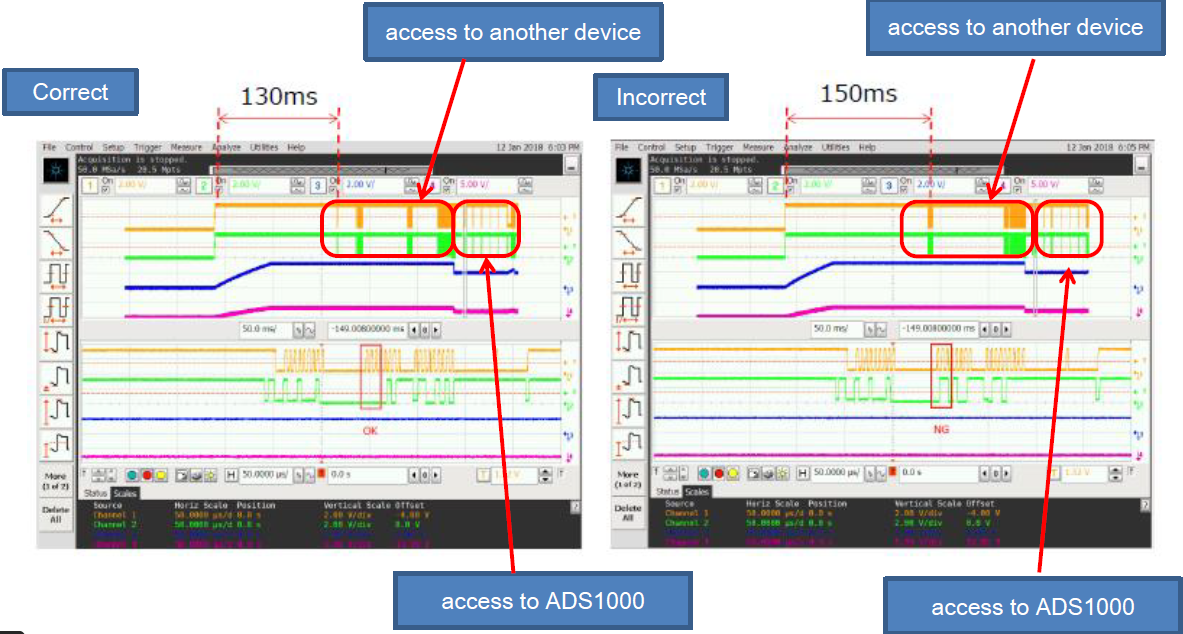
I'd also like a clearer version of these scope plots:
It is hard to read the scale and values. In the scope plots, what is the blue line? Is this power? It looks like this voltage sharply drops before the first read of the device. Is it possible that the device has gone through a brownout? Where the supply voltage drops below the operating voltage of the device?
Regardless, I'll wait for more details from the customer.
///Just to verify, these errors occur only on the first read of the device and is ok on all the reads after?
I reconfirmed the occurrence situation of the error. It occur only on the first read.
///I also want to know what communications are sent to the ADS1000 before the first reading. Is there a write command sent to the configuration register before the first read? I'd like to know what commands are sent to the I2C bus and what is read back.
The customer do not write a configuration register. They use the ADS1000 with default configuration.
///It is hard to read the scale and values. In the scope plots, what is the blue line? Is this power? It looks like this voltage sharply drops before the first read of the device. Is it possible that the device has gone through a brownout? Where the supply voltage drops below the operating voltage of the device?
The blue line is the input voltage of the ADS1000. It is not VCC.
There is an analog SW between a measurement object and ADS1000. Before the first read, the analog SW is on.
So, the input voltage of the ADS1000 drops sharply.
I'm not sure what could be causing this error in read. The only things that we could think of that might cause this type of error would be bus contention or a problem with power supply brown out.
I'll need to check what happens to the ADS1000 at power up. I had thought that device needs to be put into a conversion mode because it powers up in standby mode. This would mean that the device would have 0000h in the conversion register.
If the blue line is the analog input, at what point in the plot does the power supply
come up? Is it possible to issue an I2C general call immediately after the power supply? After that, ADS1000 should be reset and then conversions can be cleanly started.
I'll read through your new post and the attached pdf to see if I have more to add.
Is it possible for me to get a schematic? I'd like to see what other devices are on the bus and the rest of the system measurement.
Looking at the I2C line from the previous post, the configuration register looks correct, but the data looks wrong. The device is in continuous conversion mode with PGA=1 and should be outputting 12 bits of data. The ST/BSY bit is 1 which also indicates that the device is converting. However, the output data isn't showing a 12-bit data with the sign padding in the first four bits of the 16-bit format.
It's too hard to tell with the last scope plot if the power supply comes up cleanly to set the power-on reset. Also, note that the power supply must come up before the I2C lines and the analog inputs go high. If the non-power lines come up before the power supply, then there may be problems with the power-on reset. (I don't know of any specific cases of this, but I believe this is a potential problem).
If the customer cannot do a general call before reading the device, I would start with first writing to the device immediately after power and setting the SC bit to 0 so that the device is in single conversion mode. Then, after the device analog inputs are set, write to the device again to do another single conversion or set it to continuous conversion. Then wait for the conversion to complete and read the data (with the configuration register).
Again, I'm don't know what is happening with the device. I don't see anything wrong in the scope shots, but I'm hoping that there may be more to see in the schematic.