This thread has been locked.

If you have a related question, please click the "Ask a related question" button in the top right corner. The newly created question will be automatically linked to this question.

ADS1299: 2 electrode montage for a single differential/sequential channel of EEG

Part Number: ADS1299

Hello,

I am trying to acquire one channel of EEG but using only 2 electrodes.

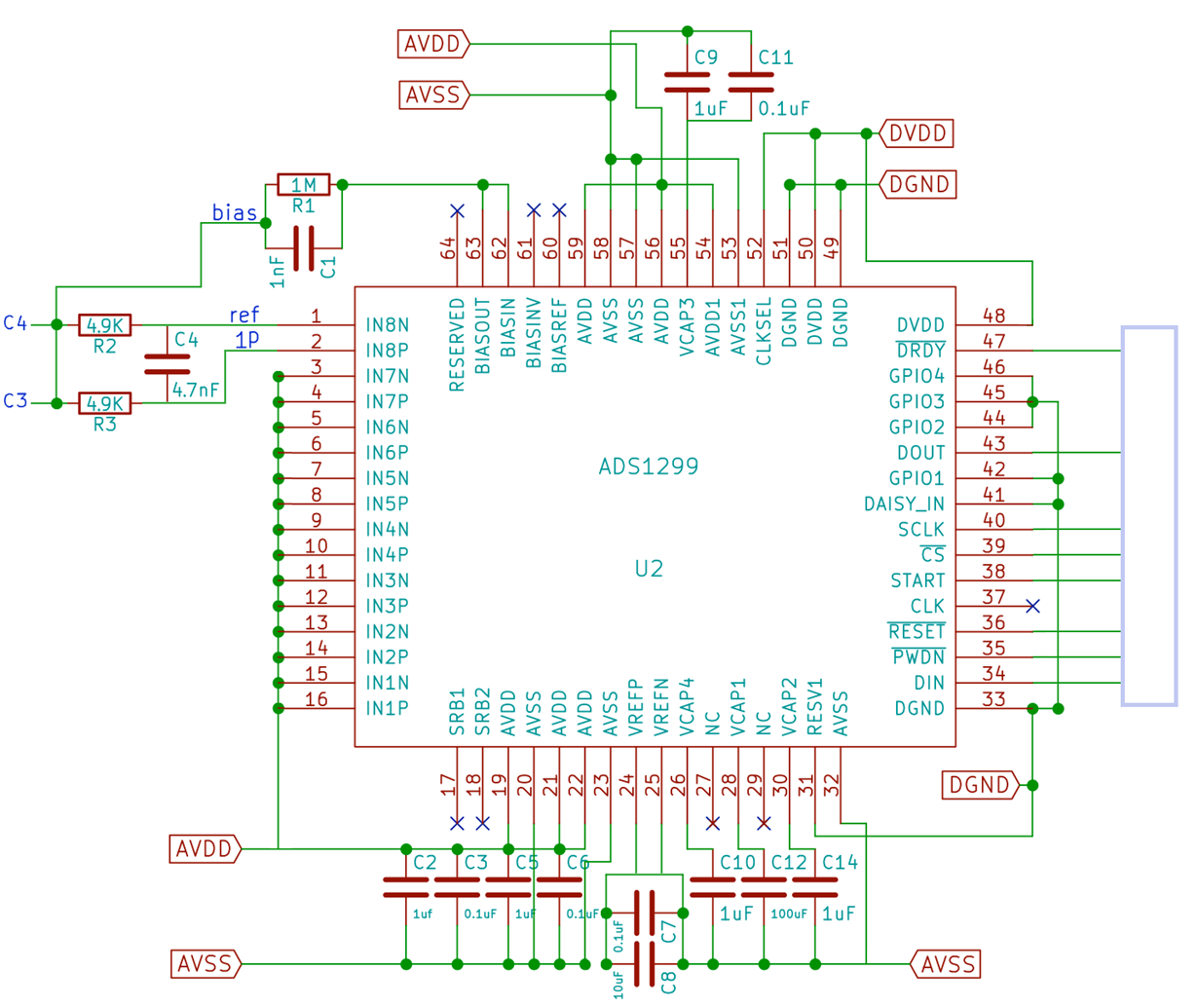
I have put together a rough schematic of how I intend to achieve this by connecting the Bias output to the + and - of the differential input channel.

1) is this possible or am I missing something?If I only include 8P and 8N in the bias, then in addition to offset, mains, etc., will there also be EEG signals which are common between 8P and 8N? Especially if for example, I am placing 8P@C3 and 8N@C4 on the 10-20 system.

2) the ADS1299 datasheet says to short unused channels to AVDD. I assume I should not include the unused channels in the bias?

3) The RC filter (Fc = 6.7kHz) between 8P and 8N is taken from Fig. 72 in the ADS1299 datasheet, using a differential capacitor instead of a shunt cap to ground to improve common-mode rejection as advised. However, in the ADS1299EEG-FE PDK, the capacitors are shunted to ground? Why is that? Should I still use the filter below if I am connecting bias directly to both 8P and 8N?

4) Finally, on a different topic, regarding decoupling capacitors, is it enough to just have them between AVDD - AVSS, or should I also have caps between AVDD-DGND, DVDD-AVSS and DVDD-DGND?

Thanks for your help!

  • Hello MarkOS,

    Thank you for the message and welcome to the E2E forums!

    1) The bias circuit on the upper left needs to be reconsidered. As it currently stands the bias electrode voltage is shorting the C4 & C3 EEG leads. This bias voltage will dominate the EEG readings. Additionally, please refer to Figure 33 and Figure 68 for how to connect this bias circuit to BIASINV, BIASOUT, BIASIN.

    2) Correct.

    3) I'll have to look in to why the capacitors on the EVM are shunted to ground.

    4) Capacitors should be placed in between AVDD & AVSS, DVDD & DGND. Capacitors in between the analog and digital (AVDD-DGND, DVDD-AVSS) planes are not recommended.

  • Hello MarkOS,

    I took a look at the EVM and believe that the capacitors being shunted to ground is not the ideal configuration. Using the differential cap as indicated by Figure 72 in the datasheet is the recommended method to prevent trace impedance mismatches. As I mentioned in my previous post, bias should not be connected directly to IN8N & IN8P.
  • Hi Alexander,

    Thank you for your reply.I am happy with 2,3 and 4. I still have some question regarding 1.

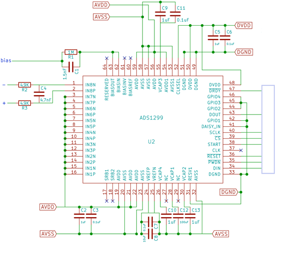
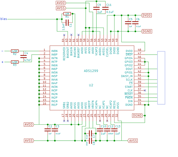
    I have redone 2 schematics, with different Bias setups, can you tell me which one is better?
    I have seen (1) used and approved in multiple threads in this TI forum and multiple commercial applications. (2) is used in the datasheet.

    (1)

    As seen in the following threads and applications.

    https://e2e.ti.com/support/data_converters/precision_data_converters/f/73/t/546300 

    https://e2e.ti.com/support/data_converters/precision_data_converters/f/73/t/257069

    http://docs.openbci.com/Hardware/02-Cyton

    (2)

    http://www.ti.com/lit/ds/symlink/ads1299-6.pdf 

    Some additional questions:

    If using (2), should I use a RC filter also in between the skin and circuit? Or just Rp as seen in Fig. 72 of the datasheet? If so what Rp value?

    As my purpose is to design a 2 electrode system for recording a single differnetial channel of EEG, can you provide any insight into how to achieve this?
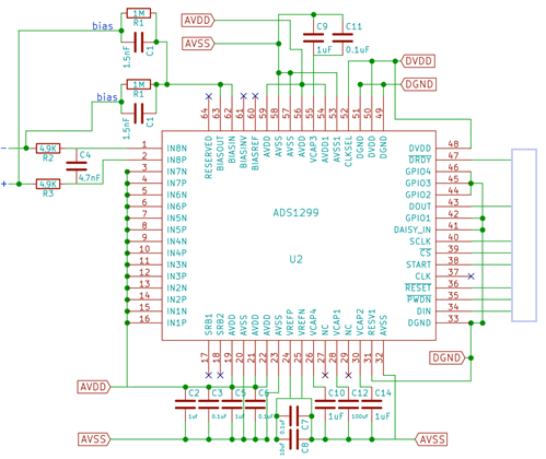
    What if I do something like below? Now I am not shorting IN8N and IN8P, but I am still applying the inverted common-mode signal back into IN8N and IN8P separately, so it should remove the common-mode signals?


  • Hi Mark,

    I have also seen the same alternative circuits for the BIAS electrode. The reason this can provide better CMRR is that the gain of the loop is much larger. At DC, the gain is set by Rf / (220k || 220k || ... ), where each 220k is the impedance between the PGAx output and the inverting input of the BIAS amplifier. By not connecting a feedback resistor (Rf), the gain will be much higher at DC and for your frequencies of interest, namely 50 Hz / 60 Hz. This creates a larger common-mode cancellation signal that is driven to the body. 

    The downside to this approach is that you can run into some stability issues depending on the other impedances in the larger feedback loop, which runs through the cables, the patient, the Channel X input, and back to the BIAS amplifier. Limiting the closed-loop bandwidth with an R-C feedback path may be a safer approach. You can still increase the gain by increasing Rf. Just make sure you reduce Cf accordingly and maintain a closed-loop bandwidth greater than 50 Hz / 60 Hz (100 Hz to 120 Hz is probably a good target).

    Protection resistance at the BIAS output is typically in the 100k ohm range to limit the DC current to the body. However, in your case, you are only using two electrodes and connecting BIASOUT directly to the inputs. I would consider AC-coupling the inputs and using a high-impedance pull-up resistor (i.e. 10M) from BIASOUT to each input electrode, like this:

    Best Regards,