Other Parts Discussed in Thread: SN74LVC1G3157, ADS114S06, ADS114S08
Hello,
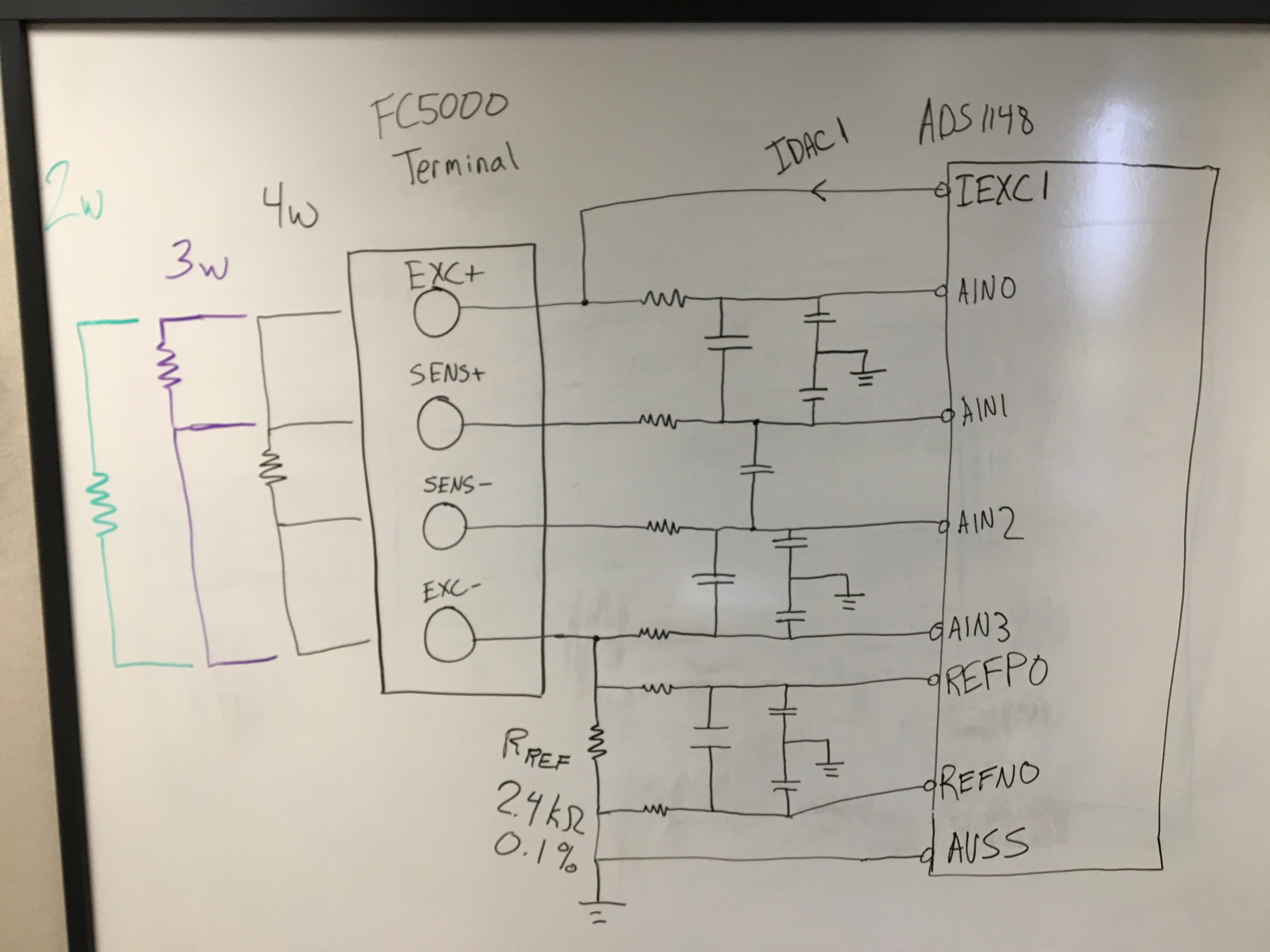
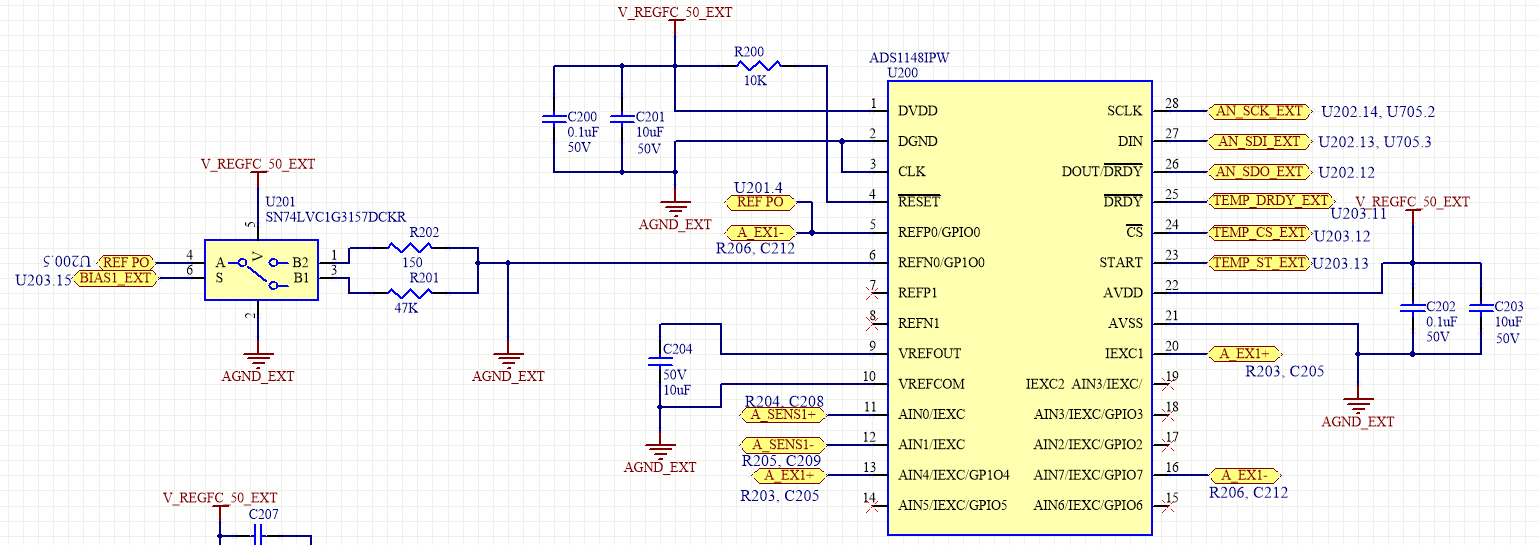
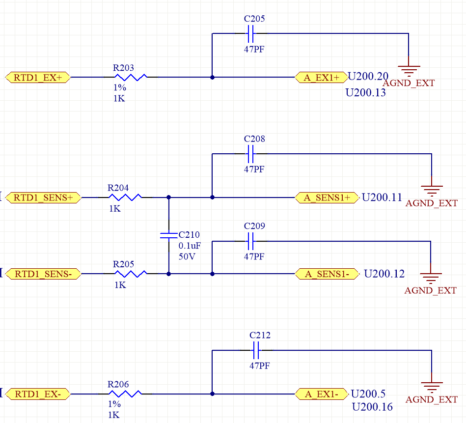
I have inherited the design below with using the ADS1148 to measure temperature from a "user-selected" 2, 3, or 4 wire RTD, or a thermocouple sensor. The design engineer is no longer around to ask about the thinking behind the design so I am coming here for some clarity. The first Image is the ADS1148 circuit, and the second image is the analog input filter circuit.
For reference, here are the settings we're using for the ADS1148:
IDAC magnitude: 1mA
Data Rate: 20 samples/sec
PGA gain: 1 V/V
IDAC source: IEXC1
R_Bias: 150 Ohm (for RTD inputs) or 47k (for thermocouple inputs), MCU switches between these resistor values.
AVDD: 5 VDC
So with this design there is no connection from IEXC1 to the input measurement or the reference input. So for a 2 wire RTD we must use external jumpers from RTD1_EX+ to RTD1_SENS+ to connect the excitation current source to the input path, and a jumper from RTD1_SENS- to RTD1_EX- to connect the current source to the reference input path. On a 4 wire RTD, we don't need the jumpers. The issue comes in when using a 3 wire RTD with this design/configuration.
I know for a three wire RTD we need two current sources. The ADS1148 tells me to source the current from AIN0 and AIN1 per our application. However, when I do this, I am picking up the 1k-Ohm offset error due to the RC filter on the analog input. This is an issue because a 150 Ohm reference was chosen and a 1k-Ohm plus RTD resistance will give full scale ADC readings because of the offset error. Would this be the correct sources to use for the 2 matching IDAC's for this application? How might I change the hardware or software to support 2, 3, and 4 wire RTD's on the same circuit? Should I be using a larger reference resistor? 2.4k?
Also, I have a question on the analog input filter. We are using 1k-Ohm, 1% tolerance resistors, per instruction from application note SBAA201. However they could be mismatched by up to 10 Ohms, which I believe to be causing some error on the measurements the ADC is getting. The filter is important for the design since the device may be in a noisy enviornment. Would going to a 0.1% or 0.5% tolerance resistor for the filter be recommended?
Thank you for the feedback,
Jonathon D.