This thread has been locked.

If you have a related question, please click the "Ask a related question" button in the top right corner. The newly created question will be automatically linked to this question.

ADS7947: Typical Input Driving Circuit ADS7947

Part Number: ADS7947

Hello,

On top of my previous question I got 2 additional questions :

1. Asymmetrial input resistor?

in the datasheet there seems to be a contradiction about the input resistor. 

On page 27 it is mentioned :

"The 470pF capacitor across the AINxP and AINxN terminals decouples the driving op amp from the sampling

glitch. It is recommended to split the series resistance of the input filter in two equal values as shown in

Figure 52."

On page 28 there is a table mentioning asymmetrical load where the resistor at AINxN is always 5 Ohms (R1) and the Rsource is totally different 


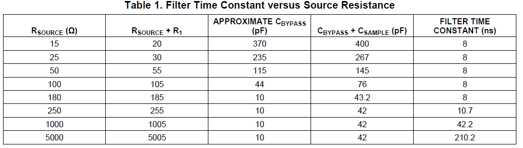
Can you explain why this table got asymmetrical load conditions on AINxP and AINxN?
Can we keep Rsource=R1= 22Ohm (in total 44 Ohm)?


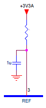
2. Decoupling of REF?

Can we use a simple decoupling capacitor of 1uF on the REF pin connected to a +3V3A (analogue power) plane ? Does it make sense to also insert a 22 Ohm series resistor to make a RC filter with the 1uF(see drawing at the right)?  Or is it better to leave this out and keep the left circuit?


Kind regards.

Filip

  • Hi F.R.,

    Figure 53 and table 1 discuss a driving circuit without a Op Amp before ADS7947, it will be critical and limited without Op Amp, the table shows the source resistance impact, the lower source resistance is expected for same specified conditions, that's why the 5ohm resistor on AINx_P is not shown. The balanced input filter can cancel the error between two input pins and actually this error is not significantly high.

    A proper value of resistor and capacitor can be found from calculation and simulation, please refer to Precision Labs - ADC training materials and video as below:

    training.ti.com/ti-precision-labs-adcs-intro-to-sar-adc-front-end

    A voltage reference is recommended to replace power supply to provide a low noise reference voltage to ADC, please refer to the link as below:

    training.ti.com/ti-precision-labs-Voltage-Reference-Overview

    By the way, please try to keep similar question about same ADC into one thread on E2E forum, thanks.

    Best regards

    Dale