This thread has been locked.

If you have a related question, please click the "Ask a related question" button in the top right corner. The newly created question will be automatically linked to this question.

ADS8688A: Possible Pinout Errata in Datasheet Diagram

Part Number: ADS8688A
Other Parts Discussed in Thread: TIDA-01576, ADS8688

Didn't know how to address this but in the current datasheet between figures on pg.3 under Section 6 - "Pin Configuration and Functions" and pg.71 figure 128, pins 3 and 4 are flipped screenshots below.

(1) 

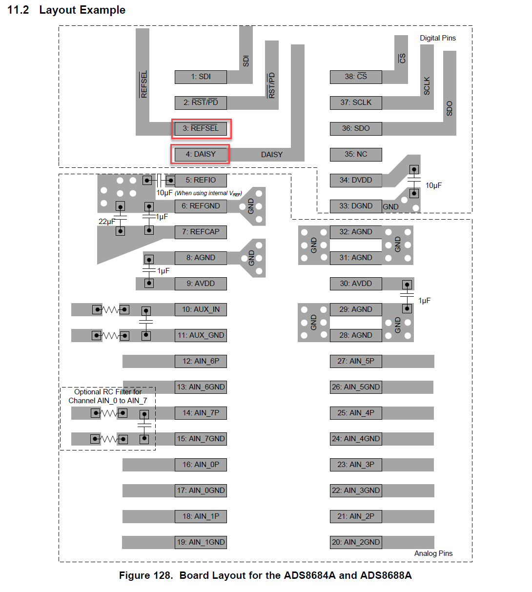
 I assume the top figure with pin configurations is correct as this is what I'm seeing consistently used throughout your schematics for both ADS866xxEVM-PDK and more importantly in your TIDA-01576 board schematics screenshots below.


TIDA-01576 Schematic Screenshot 

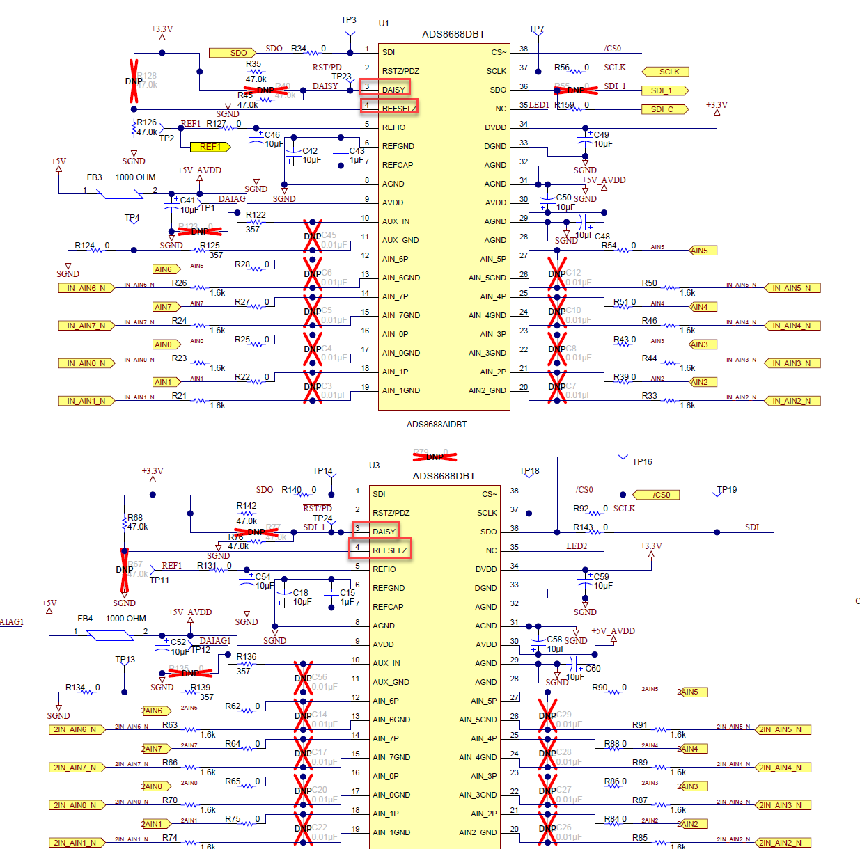
However theirs some confusion now, I just noticed in this schematic the daisy chain functionality isn't implemented with the jumper resistors R79, R77, & R55  labeled as DNP, which makes me wonder if this functionality of daisy chaining outputs together was functional with this pinout I was assuming correct... Looking for a sanity check this the first figure is correct?

Thanks

  • Hello Nathan,

    Thanks for checking on E2E forum.


    We have noticed the error in ADS8688's datasheet:  the Pinout of Daisy and REFSEL in pin configuration is correct, but the Pinout of Daisy and REFSEL in layout example is incorrect, we will correct it when update the datasheet next time.


    The Daisy pin's connection in the schematic of TIDA-0156 is correct, please refer to 8.4.1.3.1 Daisy-Chain Topology in datasheet:  The DAISY1 input pin of the first ADC in the chain is connected to DGND, the SDO1 output pin is connected to the DAISY2 input of ADC2, and so forth. The SDON pin of the Nth ADC in the chain is connected to the SDI pin of the host controller. U1's internal voltage reference is shared to U3 by connecting REFIO pins of U1 and U3 together, so the REFSEL pin of U1 is connected to GND to enable internal voltage reference, also the REFSEL pin of U3 is connected to DVDD to disable internal voltage reference.


    For the schematic in ADS86xxEVM-PDK User's Guide, it should be a mistake as well, but I will check with team and give feedback to you soon.


    Thanks.

    Best regards

    Dale