Part Number: ADC12DJ3200
Other Parts Discussed in Thread: TSW14J57EVM
Dear Sir,
I'm using ADC12DJ3200 EVM with TSW14J57EVM.
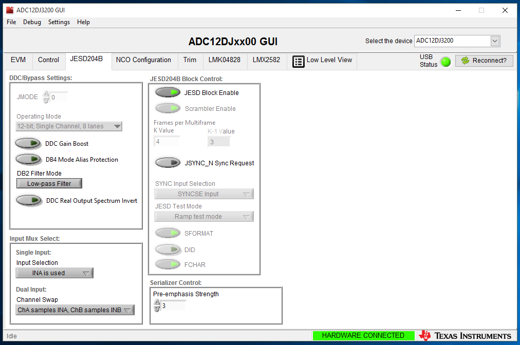
- I need to know the parameters for setting the ADC into the JESD Test Mode ? Preferably in Ramp Mode ?
- How the JESD ramp mode data is distributed across the lane during transmission ?
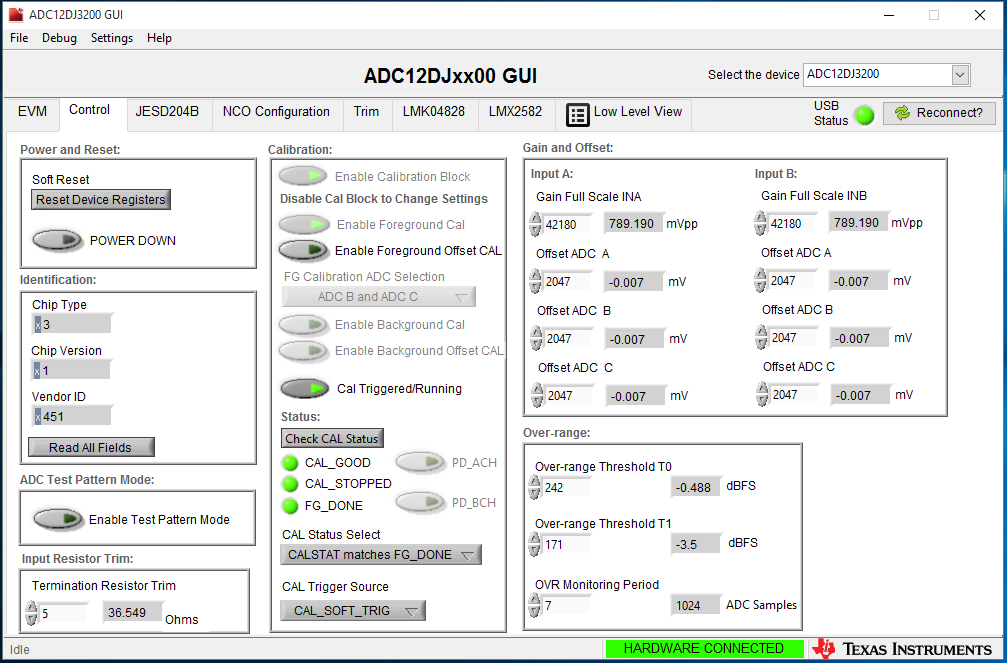
- What data is sent when "Enable Test Pattern Mode" is enabled in Control Tab of ADC12DJxx00 GUI.
- Can we verify other JESD Test Mode in this setup ? I tried. It was showing error.
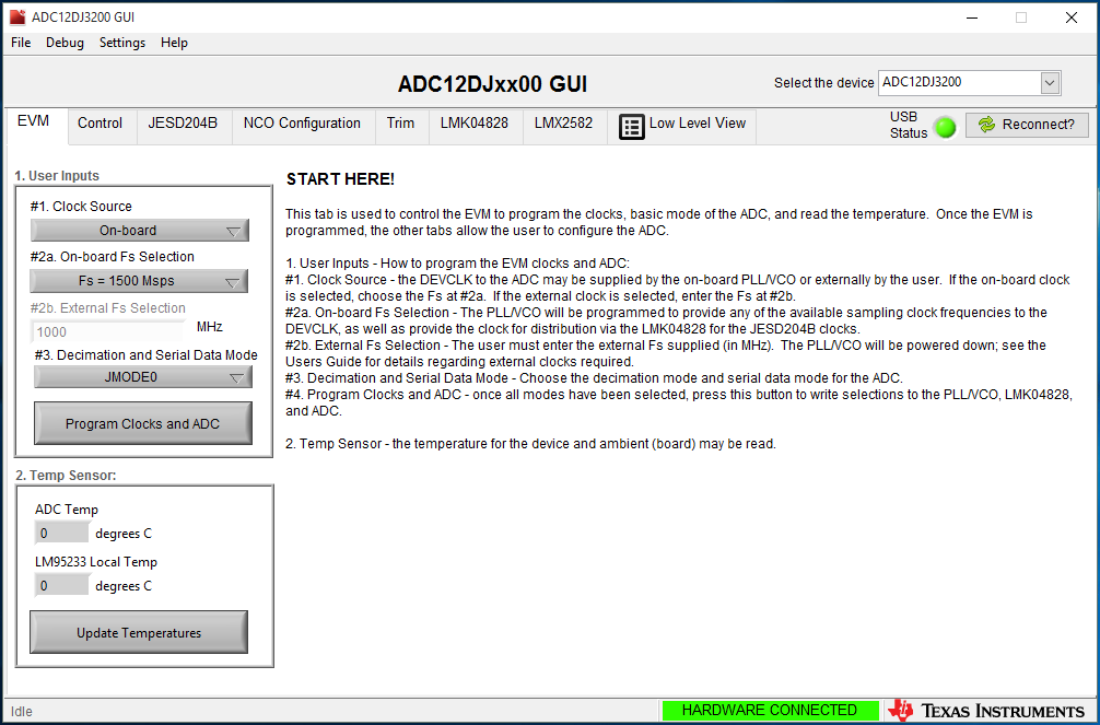
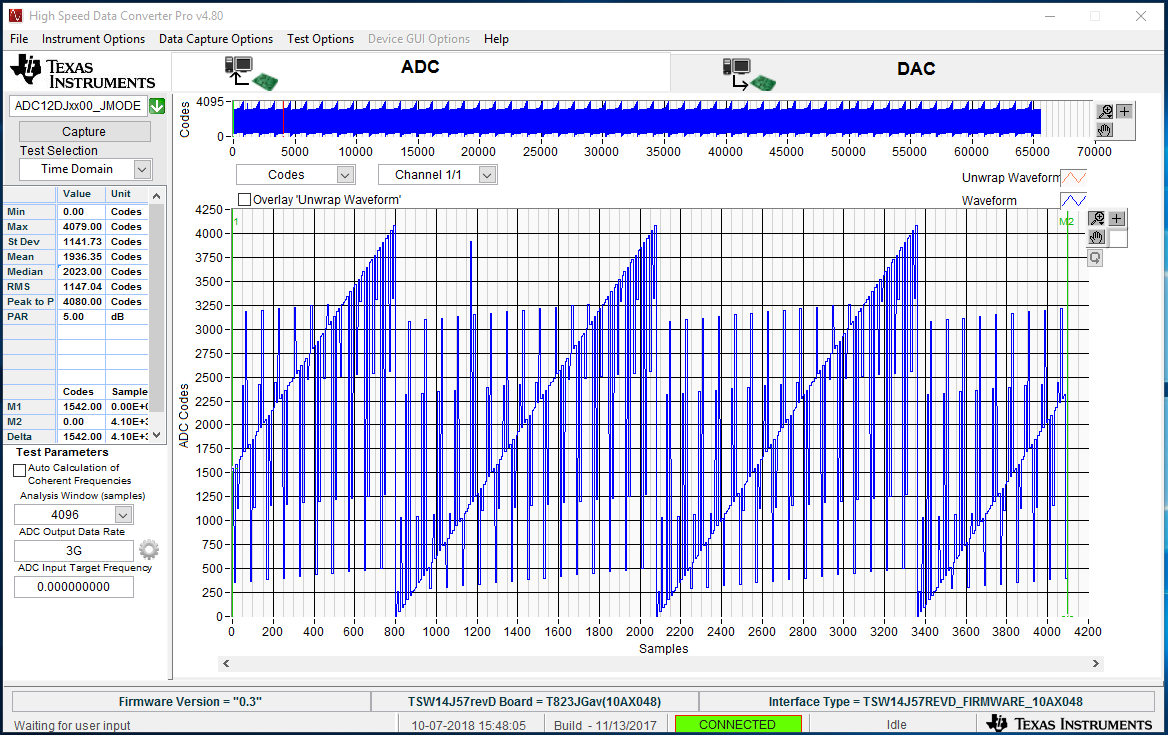
I have attached the snapshot of setting done in ADC12DJxx00 GUI and the output observed in HSDC Pro software for your information.
Thanks
With Regards,
Santanu Kumar Sinha