This thread has been locked.

If you have a related question, please click the "Ask a related question" button in the top right corner. The newly created question will be automatically linked to this question.

DDC232: DDC112 / DDC114 / DDC118 / DDC1128 / DDC2256A / DDC232 / DDC264 / DDC316 FAQs

Part Number: DDC232
Other Parts Discussed in Thread: DDC264

Hello,

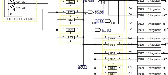
I want to use the DDC232 without an FPGA directly connected to a Piccolo controller. In my application I want to connect a photodiode-array to the chip. The output-current FS-range lies between 6uA and 6mA. So I want to use a "current divider" with a 15Ohm resistor to QGND:

Are there any experiences in connecting the DDC232 in such a way?
Are there any C-Software-Samples for the C2000 family or any other controller?

Thank You in advance.
best regards,

Kaspar

  • Hi Kaspar,

    Actually very interesting question and yes, we have heard before about similar request although I do not know the outcome. The circuit I recommended is exactly the same as you draw (basically a resistor divider, but for current).

    #1. One key thing to take into account is that input voltage on the amplifier (say at pin N1-G3) changes with signal (basically it has a non-zero input impedance). Unfortunately I cannot see in the datasheet this kind of plot but if you look on the DDC264 you can see that in fig. 15 and 16. For full-scale current inputs and depending on the range, the value can be 3mV. In the case of the DDC264, that means that in range 3 (maximum range) for an input current of 150pC/166us=0.9uA the input of the DDC (in your case voltage at pin N1-G3) is 3mV. I.e., zin=3.3kOhms.

    Bottom line, you cannot assume that the input node of the amplifier is exactly zero. Nevertheless, you can do your calculations assuming that it is a constant impedance to ground. I have not characterized how linear that impedance would be but discussing here, we feel that it would be as linear as the device linearity so, working with a constant Zin may be good enough.  

    #2. A second potential thing related to the first is that the impedance may not be perfectly constant with temperature. So, something to watch for. If you can do calibrations, as part of your gain calibration, it probably will account for these two factors (Zin and Zin vs T).

    #3. Another thing to watch for is that the voltage at the anode of the diode will not be constant but will also change with signal. That means that you probably need to bias the diodes (apply a positive voltage at the cathode) so that the diode is always reverse biased and as such, the leakage current doesn't change too much. But we think it will and and as such it may affect the measurement accuracy in a non-linear way (not easy to correct for).

    #4. Finally, I can see a case where the resistors at the input add noise, but we did some quick back of the envelop calculations and it looked like it may be fine. Making them bigger helps but this is a trade-off with #3 (bigger means more voltage across the diode)

    No promises, but we may try this in the lab and report back on 1, 2 and 4. We can't do 3 as we do not have the PDs and may change from diode to diode (?) If you try it, it would be really good if you share the results in this forum, for others to learn from it... Of course, your call...

    Regards,

    Eduardo

    PS.: As for the software, I am not aware of the MCUs our customers use... Maybe someone else knows of a code example and can reply...