This thread has been locked.

If you have a related question, please click the "Ask a related question" button in the top right corner. The newly created question will be automatically linked to this question.

DAC8740H: hart communication problem in 3 wire 4-20mA

Part Number: DAC8740H
Other Parts Discussed in Thread: DAC8760

Hello ,

We are designed 3-wire circuit 4-20mA with Hart. but we faced some Problem. Please find schematic and rectify it,

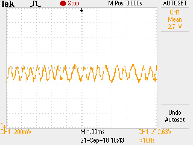
In slave transmitter Hart schematic, We are successfully sending hart signal with 4-20mA output, But in that process we required Load resister More than 350 ohms. can you tell me what we can do to used minimum 250 ohm load resister.

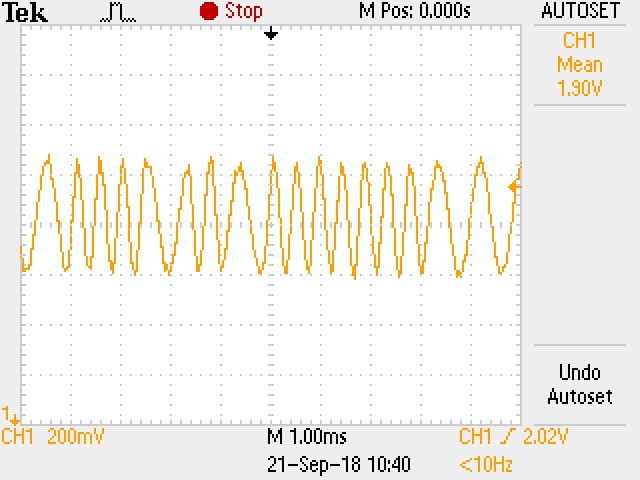
In master communicator Hart schematic, We didn't receive response,Please checked schematic suggest us changes if required.

How to increase peak to peak mV range of hart signal in slave and masterMASTER_COMMUNICATOR_HART.PDFSALVE_TRANSMITTER_HART.PDF

  • Hi,

    One issue I notice with your schematic is the AC coupling capacitor on MOD_OUT (C32) is 2.2nF. This capacitor forms a filter with the load resistor and using a small value will attenuate the HART signal from MOD_OUT. I would recommend changing this capacitor to a value around 2.2uF.

    Your attached schematic does not show how you are connecting the load resistor or current input (HART slave). Can you provide these details?

    Thanks,
    Garrett
  • Dear Garrett,

    I have done these changes, still hart does not responding on less than 370 Ohm load resister. Please checked updated schematic.

    Currently we are using other make hart communicator to communicate with pc. but we want to make our own communicator or master device.

    As you can see in master communicator hart pdf, we make this circuit but it couldnt convert receive or transmitt hart signal into digital form. Also it received very low peak to peak voltage approximetly 10 mV peak to peak.7271.MASTER_COMMUNICATOR_HART.PDFslave_xmitter_hart.PDF 

  • Hi,

    So to confirm, the transmitter can communicate with the HART communicator connected to the PC but not your HART master circuit? Is your HART master circuit able to demodulate the data sent by the transmitter?

    Can you provide waveforms of the MOD_OUT, HART_IN, and the HART waveform voltage across the load resistor. The HART waveform should be at least 120mV across the load resistor for DAC8740H to demodulate it.

    Thanks,
    Garrett
  • Hello,

    we faced problem, when we connect Mod_out signal with mod_in signal in master circuit( c32 and c36 link connection, can you tell me zener diode value D8? is it mandatory? currently we are not using D8 ),

    Master mod_in side we get 150~175mV peak to peak , this happened only when we connect C36 and C32 link each other, But when we disconnect c36 and c32 link and apply Iout directly to c36 that time we get 250mv peak to peak waveform, And hart send us proper output .

    and same thing happened with mod_out signal1106.MASTER_COMMUNICATOR_HART.PDF6278.slave_xmitter_hart.PDF. It will send data without C32 and C36 Link.

  • hello ,
    I have added 10 ohm resister in between c36 and mod_in input with shorting c32 and c36 link. Now master can read signal that send by transmitter. Now i am trying to transmit master data signal to slave transmitter, and i got waveform upto R25 resistor but later at C32 output point(IOUT) it goes to zero.
  • Hello,

    D8 is not required.

    The master MOD_IN HART signal will simply be the HART current waveform from the transmitter divided by the load resistance. It looks like you are using two different methods at the same time to couple the HART signal into DAC8760. I would suggest either using the HART-IN pin if you are using 4-20mA range or the high pass filter to ISET-R if not, but not both at the same time.

    Your master schematic still shows the 2.2nF for C32. Is this what you are using? If so the master will not be able to modulate the HART signal on the loop. I wouldn't recommend shorting MOD-IN and MOD_OUT directly, they should be capacitively coupled.

    Another issue I notice with your transmitter schematic is your external NPN boost configuration. R34 should not be there and is in the path of both IOUT an the alternative boost path for the current output. What DC current are you setting? I am guessing it is not being correctly regulated as R34 significantly reduces the current drive capability.

    Thanks,
    Garrett
  • Thank you Garrett,

    0 ohm resister at R34 has solved my Load resister problem, now I can Read hart signal at 250ohm resister.

    I forgot to make change of 2.2nF, after connecting 2.2uF at C32 master start to sending data to slave, Now my both way communication start properly, Only problem is some time my slave device missed some byte when he receiving query from master.
    For example My Master sending query-:0xff 0xff 0xff 0xff 0xff 0xff 0xff 0xff 0xff 0x01 0x02 0x03 0x04 0x05 0x06 0x07 0x08 0x09 0x10 0xff 0xff 0xff 0xff 0xff

    I have sending above query after every 3 sec.and my slave read this like,
    0xff 0xff 0xff 0xff 0xff 0xff 0xff 0xff 0x01 0x02 0x04 0x05 0x07 0x08 0x09 0x10 0xff 0xff 0xff 0xff
    or
    0xff 0xff 0xff 0xff 0xff 0xff 0xff 0x01 0x02 0x03 0x05 0x06 0x08 0x09 0xff 0xff 0xff likewise

    As you can see slave missed to received some byte but this not happened every time some times my slave shows proper query but this happened very rare means ones's in 4 to 5 query.
    I have write test code for this.and read response on another serial uart port of slave cpu. my Uart port work accurately that i test in my UART test code, he doesn't missed any data when i was sensing query through PC uart port.

    But when i do reverse operation means my slave send same query to master that time master received proper query every time. he doesn't miss any byte.
  • Hello,

    How are you handling the carrier detect pin in the transmitter software. I could see missing some data if there is a delay between the carrier detection assertion and the MCU handling the UART data. But this may not be the issue.

    Can you provide a scope capture of the load resistor voltage when the slave is sending HART and when the master is sending HART?

    Thanks,
    Garrett
  • Hi,

    Please find below schematic for master communicator sending data to transmitter.

    Please find below schematic for transmitter sending data to master communicator.

  • Hello,

    The amplitude levels look reasonable but for the master I can't tell if the waveform is distorted or just under sampled on the scope. Also, are these reversed? I would expect the master to be ~500mVpp and the slave to be ~250mVpp.

    Thanks,
    Garrett