This thread has been locked.

If you have a related question, please click the "Ask a related question" button in the top right corner. The newly created question will be automatically linked to this question.

ADS5294: Need to use SYNC across multiple devices when NOT decimating.

Part Number: ADS5294

Hello,

I wanted to provide an update on the resolution to the related thread regarding the use of the SYNC pulse to align multiple ADS5294 ADCs even when NOT using decimation. We were told by TI to use the SYNC in these instances and we are finding that it does seem to work – but not 100% of the time.

We implemented the SYNC and found that some of the time the application of the SYNC pulse simultaneously across 2 ADCs does not prevent our ADC samples from becoming misaligned. After sending the pulses, they still appear misaligned (i.e., off by 1 sample from each other) about 10% of the time based on the testing that we have done so far.

Note that after re-issuing the SYNC multiple times they do always end up eventually realigning.

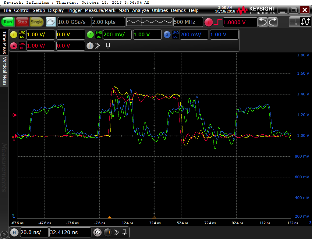
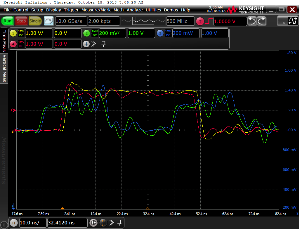
I’ve attached some screenshots showing the SYNC pulses (red and yellow traces) and ADC sample clock inputs for both ADCs (blue and green traces). These were taken with a 20 MHz sample rate and no decimation. Disregard the over/undershoot as our probe grounding was not great.

  1. Do these traces look compliant with what is expected for the setup/hold time of the SYNC with respect to the sample clock inputs?
  2. What is the reliability of the sync pulse and are you aware of any reason why they would require multiple sync pulses?  If there are instances where multiple SYNC pulses are required, is there a certain minimum number that we should program into our software?
  3. Are there any register settings we need to make to ensure consistency?

Thank you,

Bob


  • Hi Bob,

    How are you?
    Thank you very much for the detail description about ADS5294 SYNC issue.
    This is very important to us.
    We will forward this to our system engineer
    and reply to you very soon.

    Thank you so much again!

    Best regards,
    Chen
  • Hi Bob,
    How are you?
    I have mentioned this issue of ADS5294 to our group.
    Here are they want to know:
    1) please send us your register settings from ADS5294 registers used for SYNC set up.
    Thank you!
    2) please check the synchronized SYNC pulse with ADC Clock (at very close to the devices' pins).
    3) for the SYNC, the trace length must be matched each other across devices.
    4) if possible (same as our ADS5294EVM did), please tie 50 ohm termination to GND
    at very close to each SYNC pin location.
    5) Every time before run a new SYNC pulse, please RESET (by setting register) as:
    (note: this following is the ADS5294 GUI's Software RESET.)
    (In this setting, we are using 14bit mode, LSB-first, Offset Binary modes)
    set: Address=0x00, Data=0x0001
    set: Address=0x00, Data=0x0000
    set: Address=0x42, Data=0x8000
    After that, then please re-run SYNC pulse on your multiple devices.

    Thank you very much!

    Best regards,
    Chen
  • Thanks, Chen,

    We will gather this information.  For 2) above, we could use some further clarification.  When you say "check the SYNC pulse", what specifically are you/we looking for? Did our scope traces seem correct?  Was there anything that you were concerned about?

    Regards,

    Bob

  • Hi Bob,

    How are you?
    Our group engineers mentioned that
    could you please set the following RAMP Test Pattern mode for the use of the SYNC pulse?
    by setting the following Registers first (before doing the test):
    set Address=0x25, Data=0x8040
    set Address=0x02, Data=0x2000

    Thank Bob a lot!

    Best regards,
    Chen
  • Thanks, Chen,

    We are working your recommendations in the following order and will get you the results when we implement them:

    1. Dump our register settings and send them to you.
    2. Perform the SW reset prior to the SYNC.
    3. Perform the RAMP SYNC test.
    4. Scope traces of the SYNC as close to the ADC pins as possible. SEE QUESTION BELOW.
    5. If we can find a suitable location, we will try to terminate the SYNC with a 50 Ohm resistor.

    For #4, since we already sent you the scope traces showing SYNC, can you please tell me what concerns you have and what specifically you might be looking for in the waveform? E.g., do you want to see them relative to the sample clock? Do you want to see both ADC's SYNCs on the same trace, etc.?

    Regards,

    Bob

  • Hi Bob,

    Thank you for detail explanation.

    Yes, for the #4 we have seen the scope traces which is showing the SYNC and Clock signals.

    It looks close to the datasheet's plot,

    so please don't worry about this concern from us.

    Thank you!

    For #2, we know it could be either not easy or no space at all

    to place the 50 ohm resistor. Then this is just an option.

    If impossible, then please just leave the way you have.

    Because as you can see, from our ADS5294EVM schematics

    (you can see it from the ADS5294 user's guide), the ADS5294EVM has

    a 50ohm termination used for SYNC input pin.

    Also could you let us know that maybe you have built on

    your own test board that has multiple (at least two) ADS5294 devices soldered on it, right?

    And SYNC signal was layouted to share multiple ADS5294 devices, right?

    Thank you very much!

    Best regards,

    Chen

  • Thank you, Chen.

    With respect to your questions, see below:

    Also could you let us know that maybe you have built on your own test board that has multiple (at least two) ADS5294 devices soldered on it, right?

    Correct. Actually, each of 2 ADCs is on a separate board but receives the same aligned sample clock and SYNC (as evidenced by the screen shots).

    And SYNC signal was layouted to share multiple ADS5294 devices, right?

    Correct, with the same trace lengths.

    Regards,

    Bob

  • Hello, Chen,

    In the following sequence that you recommended originally, can you please explain why you asked us to set 0x42 bit 15 to a 1? This seems only to have effect if using it along with bit 3 of the same register and then only if F0(15) is set to 1.

    5) Every time before run a new SYNC pulse, please RESET (by setting register) as:
    (note: this following is the ADS5294 GUI's Software RESET.)
    (In this setting, we are using 14bit mode, LSB-first, Offset Binary modes)
    set: Address=0x00, Data=0x0001
    set: Address=0x00, Data=0x0000
    set: Address=0x42, Data=0x8000

    Thanks,
    Bob
  • Hi Bob,
    How are you?
    That is because when we are using ADS5294 GUI
    and clicking on its "Soft Reset" button for doing reset by using register setting.
    And you are correct,
    the register setting 0x42, 0x8000 looks like it does not do anything.
    (also it does not set any other register as you mentioned 0xF0(15) at all.)
    I also double checked the ADS5294 schematics.
    It is only set up (was designed before) internal mode.
    Therefore, please just ignore this 0x43, 0x8000 setting.

    Thank you very much!

    Best regards,
    Chen