This thread has been locked.

If you have a related question, please click the "Ask a related question" button in the top right corner. The newly created question will be automatically linked to this question.

ADS1262: Voltage measurement drift

Part Number: ADS1262

Hi,

i'm working with ADS1262 on a Protocentral Board measuring a wheatstone bridge load cell.

The board is beeing powered by arduino +5VCC supply, which is not a stable power supply.

The load cell is being powered by another voltage supply (a 3.7V Batery) and its diferential voltage, which is 0 when balanced, read by AIN0 and AIN1 of ADS1262.

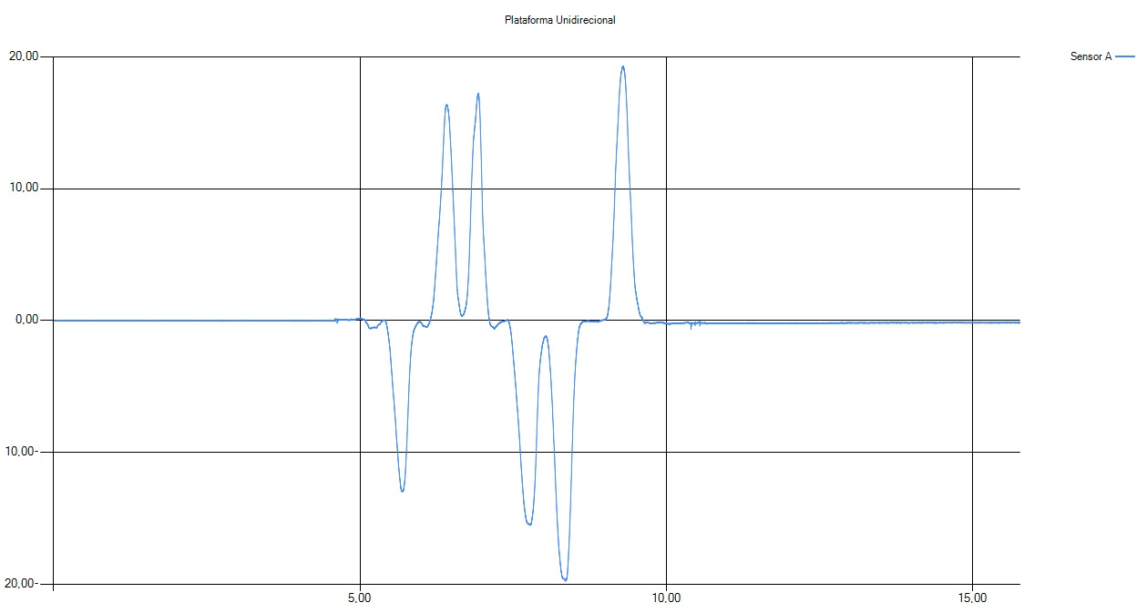
The problem is that I'm getting voltage imbalances during its operation as shown in the pictures below. The voltage  after the force test should be the same as before (near zero).

But this doen't not happen. The voltage in the load cell remais the same as before, otherwise the voltage on +5VCC of arduino changes. Is that the source of the imbalance? If it is, why this happens even if I'm using +2.5V internal reference? 

Thank you.

  • Hi Eduardo,

    How is the 3.7V (battery) voltage referenced to the ADC, it is floating or does it connect to the ADC ground?

    I would recommend trying to measure the bridge ratiometically. By this I mean, that you take the excitation voltage (used to power the bridge) and route it to the ADS1262 (pins AIN2 and AIN3, for example) and then configure the ADS1262 to use an external reference ( AIN2/AIN3 in this case).

    In this way, if your excitation voltage changes, the ADC's reference voltage AND bridge voltage will change proportionally. Since the ADC is measuring the ratio of VIN/VREF, you should see that the ADC conversion remains much more stable.
  • As always, thank you for the fast reply.

    How is the 3.7V (battery) voltage referenced to the ADC, it is floating or does it connect to the ADC ground?

    I've made tests in both ways, with batery negative floating and connected to ADC ground (which is arduino ground). Both ways the result are quiet similar.

    I would recommend trying to measure the bridge ratiometically. By this I mean, that you take the excitation voltage (used to power the bridge) and route it to the ADS1262 (pins AIN2 and AIN3, for example) and then configure the ADS1262 to use an external reference ( AIN2/AIN3 in this case).

    I've done that setting Registers:

    POWER from 0x11 to 0x10

    REFMUX from 0x00 to 0x12

    The error is still happening, the pictures as follows. On first pic 3.7V batery ground is not connected to ADC groud and it is connected in the second picture.

    This makes me think ADC power supply (+5Vcc arduino) may be affecting the measurements.
    Another point that I just notice is the power supply is violating ADC recommended analog power supply operating range (its floates around 4.65V to 4.80V) and datasheet says 4.75V to 5.25V. 

  • Hi Eduardo,

    Do you have a 5V bench supply that you can use to power the ADC + bridge?
    I'd recommend using the same supply to excite the bridge as well as the ADC, this way you'll know that the common-mode output voltage of the bridge is within range of the ADC. In this configuration you could either route the bridge excitation voltage back to the ADC or just use the internal AVDD-AVSS reference.

    Floating the battery with respect to the ADC ground certainly will have issues. Connecting it to ground should provide better results, but perhaps this connection is too long and causing issues.


    Also, do you have any way of knowing if the load cell has any memory to it? If you take a longer data set does the measurement eventually return to the zero set-point?