This thread has been locked.

If you have a related question, please click the "Ask a related question" button in the top right corner. The newly created question will be automatically linked to this question.

ADS1298 Decoupling/Bypassing

Part Number: ADS1298

Hi,

I have some questions about decoupling/bypassing capacitors placement. My design uses bipolar supply mode. The datasheet recommends the placement of the mentioned capacitors like depicted bellow

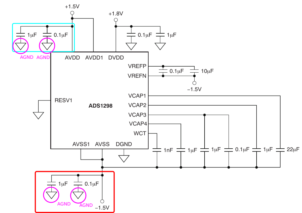
As depicted, we have the configuration AVDD-AGND and AVSS-GND. But in layout section of the same datasheet we have the following picture which states "The example circuit is shown for either a single analog supply or a bipolar-supply connection."

As depicted, the recommended configuration now is differential (AVDD-AVSS). The ADS1298ECG-FE schematics employs the differential decoupling method (AVDD-AVSS) like depicted bellow

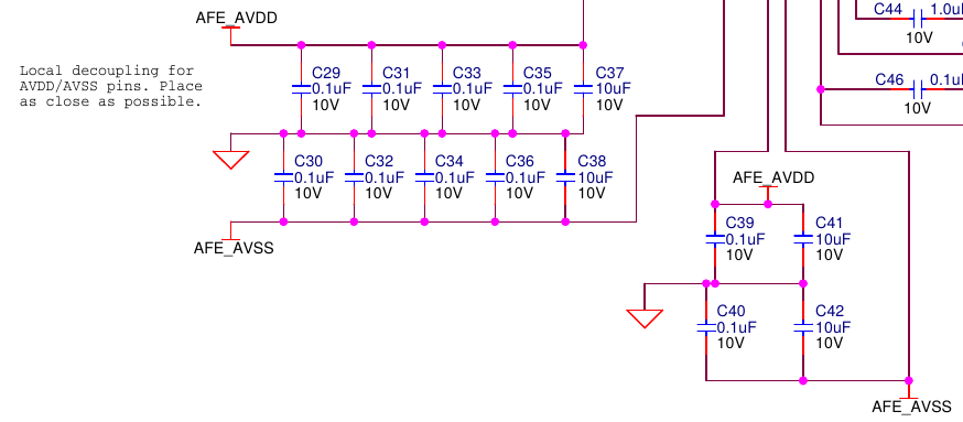
but the AFE-ADS1X9X-MVK MAVRK module from TI does different, employing the common mode decoupling (AVDD-GND and AVSS-GND), like depicted bellow

I found the following link at TI e2e forum, but the things remains unclear to me.

  • Hi Otavio,

    Thanks for your excellent and well thought out post!

    I think Ryan summed it up nicely in the thread that you linked; for the power supply caps, between AVDD and AVSS, for the input filtering caps, tied to GND or AVSS. The main thing is that the voltage difference across the cap is maintained so that it remains charged and can provide that extra sink or source during power up or if there's a small hiccup in the power supply. Remember that for capacitors a DC voltage looks the same as GND since there is not a change in voltage over time (dV/dt).

    In the layout picture, you can assume that the input caps are tied to AVSS since it is the same symbol. The AFE-ADS1X9X-MVK MAVRK module is built by a different group (and designed by different people) from the ADS1298EVM-PDK. Their decision most likely came down to preference or layout configuration.

    Please let me know if this description is not clear or if you have additional questions!
  • Hi Alex,

    First of all, thank you for devote some of your time to ask my question!

    - Regarding the input filter grounding, I think that is clear for me. I'm really convinced!

    - Regarding decoupling, I'm not sure. I assume that both differential and common mode decoupling actually is right. Common mode is recommended in power supply section of datasheet for bipolar configuration, whereas only differential decoupling is depicted in layout section of datasheet. I think datasheet is confuse, because of this picture

    I do not know, but I believe that ADC of ADS1298 internally do not cares about GND ground, which explains the differential configuration suggested by Ryan Andrews. Summing up:

    - Datasheet suggest common mode at one section and differential at another.

    - ADS1298EVM-PDK uses a mixed common mode and differential decoupling, but differential decoupling predominates.

    MAVRK ADS1298 Module uses common mode decoupling only.

    Ryan Andrews suggest the differential decoupling approach.


    In doubt, I will use ADS1298EVM-PDK as a reference, because I'm satisfied with the performance for now. Sorry, I'm rarely develop circuits which uses dual supply, therefore, decoupling is new for me in bipolar supply applications.

    Thanks Alex.

    Regards,

    Otavio Gomes

  • Hi Otavio,

    You're most welcome!

    Following the ADS1298EVM-PDK is a great choice!
    Please let us know if you have additional questions!