This thread has been locked.

If you have a related question, please click the "Ask a related question" button in the top right corner. The newly created question will be automatically linked to this question.

ADC34J45: Convert ADC code to Voltage

Part Number: ADC34J45

Dear All,

Hi.

I'm using ADC34J45EVM with TSW14J56EVM.

I have a question about converting the ADC code to the corresponding voltage value.

I read this blog post:

#e2e.ti.com/.../it-s-in-the-math-how-to-convert-adc-code-to-a-voltage-part-1


But unfortunately, I could not achieve what i was looking for.

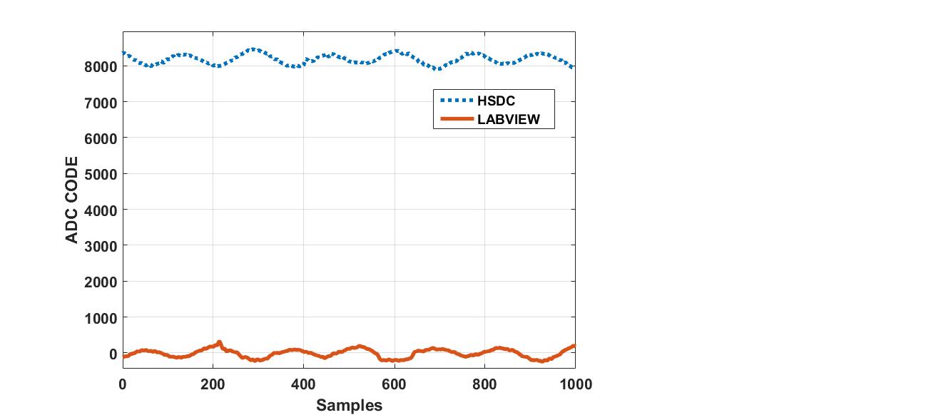
When I capture data using HSDC pro software the ADC code for the captured signal ranges from 8000 to 8400. Using LABVIEW for nearly the same input, the ADC code varies from -200 to 200 which I think is technically the same thing.

The question is, for this particular unit, what is the proper way of converting the ADC code to voltage? In HSDC pro I can easily select voltage for the Y-axis but in LABVIEW I need to convert the values myself.

I could not find any predefined function of this particular subject in HSDCPro Automation DLL user Guide.

Thanks.

Fernando

  • Hi Fernando
    One of our ADC experts will provide a detailed response soon.
    Best regards,
    Jim B
  • Hi Fernando,

    With an idle input (no connection/termination on analog input), I am observing a code count around ~8200 on channel 3 and channel 4. This seems realistic since our full-scale value is 16383, and the analog input is being biased to the mid-scale point by the common mode voltage (VCM).

    The generic equation to find the voltage from the output code is


    Where LSB is 


    Since this is a 14bit converter with a voltage reference of 2V, we can use the equation as follows.

    If you measure the DC voltage present on R29 or R41, you will see a reading close to that (I'm seeing almost 1V).

    Best Regards,

    Dan

  • Dear Dan,

    Thanks again for your quick and useful reply.

    Honestly, I do not have access to the board right now but from the data that I've recorded, I see the voltage typically have a value of -0.1 to 0.1 V (when I've selected voltage for the Y-Axis in HSDC Pro). If I'm correct, according to the 3rd equation, the ADC code for that should be ~800 which I highly doubt.

    I'll definitely check it later.

    My question is:

    Why the ADC code is (8000 to 8400) in HSDC while it is (-200 to 200) in LABVIEW with absolute no modification? Is there anything that I should do in LABVIEW? Because definitely the correct values should be used in the 3rd equation.

    This picture is from a nearly similar input to the ADC.

    Thanks.

    Fernando

  • Hi Fernando,

    Thank you for providing the graph. This looks like a 2's Complement / Offset Binary issue. HSDC Pro is using offset binary to interpret the voltage value. We are saying the same thing, just using a different language!

    For offset binary, we scale from 0 to 16383 codes, and, in 2's complement, we scale from -8191 to +8192. So, you seeing a swing of approximately 200 codes around 0 is ok. There are tools available online to convert between 2's complement and offset binary.

    You can also change the data output format of the ADC by writing to the register below.


    Best Regards,

    Dan