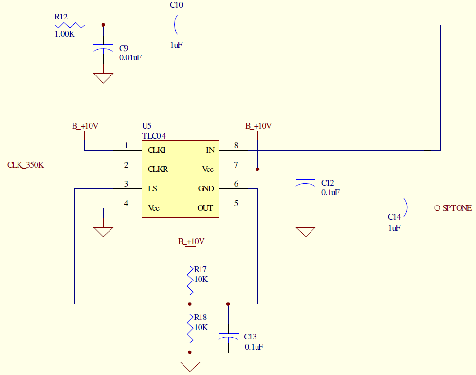
I am using the TLC04 in a single supply operation. It would appear that I need to use the circuit from Figure 6 of the latest datasheet. From this figure and the "Terminal Functions" table on page 2 of the datasheet, I have the part connected as follows (schematic pasted at the end of this post):
Pin Connection
1 +10V
2 350KHz clock, 0 to +5V
3 +5V: A +10V/2 voltage divider (10K to 10V, 10K to GND, with 0.1uF to GND, same as pictured in datasheet)
4 GND
5 Filter out (AC coupled)
6 pin 3
7 +10V
8 Filter in (AC coupled)
I have successfully used this device with a +/-5V supply, but in the above configuration, it is not passing signals that are in the expected passband (350KHz/50 = 7 KHz, lowpass).
Full disclosure: The +10V input is actually about +10.6V and is heavily filtered with a series 20 ohm resistor, a 1000uF cap to GND , and a 0.1uF cap to GND prior to the TLC04 +10V net.
Am I missing anything?
Thanks!