This thread has been locked.

If you have a related question, please click the "Ask a related question" button in the top right corner. The newly created question will be automatically linked to this question.

AFE5808A: AFE5808A Frame Clk issue

Part Number: AFE5808A

Dears.

I need help with the problem of the AFE5808A.

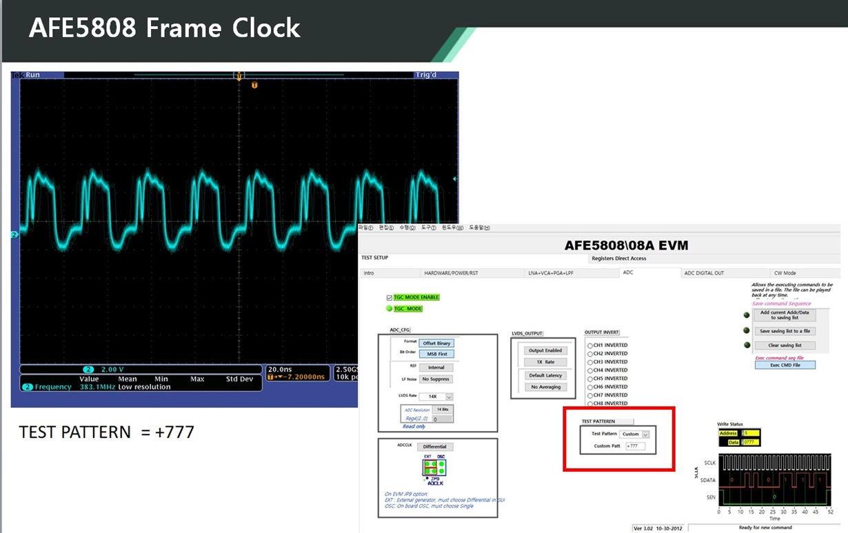
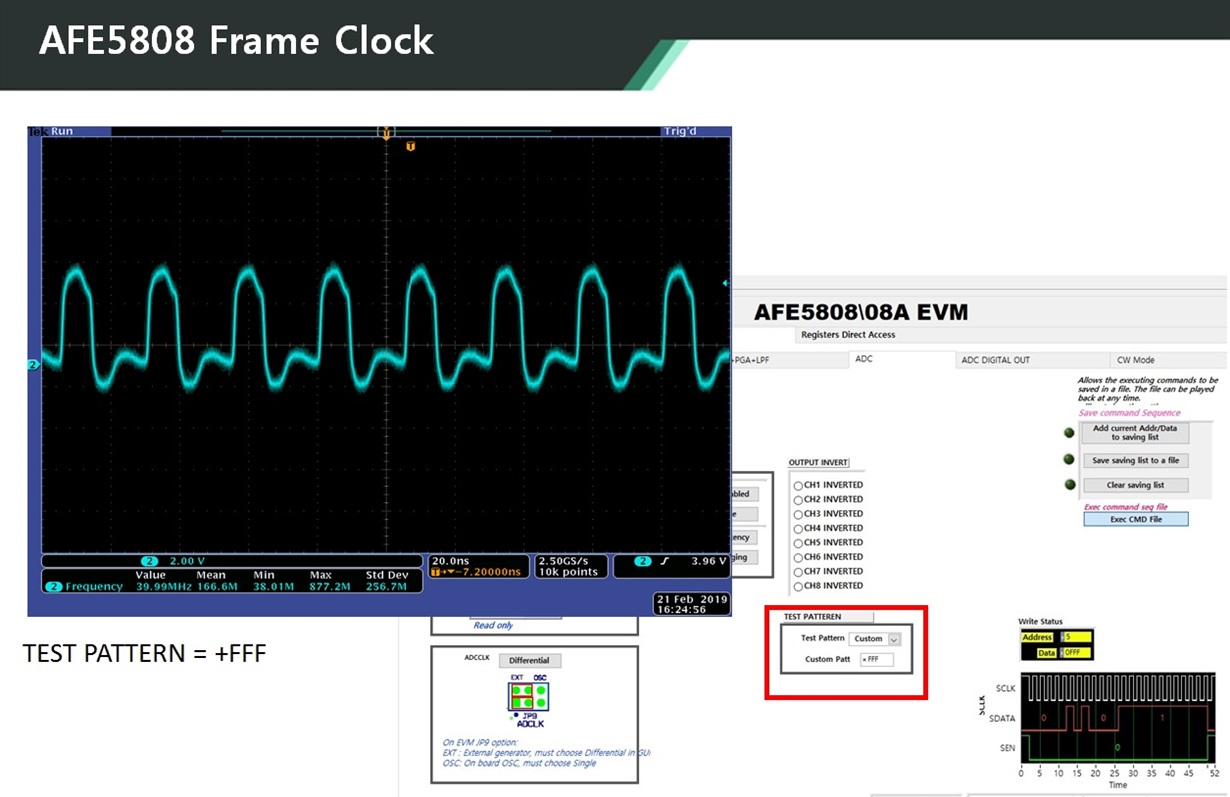
When Frame_CLK of AFE5808A is inputted to FPGA (Cyclon 4), inputting "TEST PATTEREN" custom data in UI of AFE5808A changes Frame_CLK of AFE580A.

Does Frame_CLK change depending on the value of the custom data input?


Thank you.


  • Hi HENRY,

    How are you?
    Thanks for using AFE5808A device.
    I will look into your question very soon,
    and will return to you in 2-3 days.

    Thank you and best regards,
    Chen
  • Hi Henry,

    How are you?
    Thanks for showing us two pictures.
    First question is: what does the blue signal shown on the picture stand for?
    Second question is: Does this blue signal can make the output signal not working correctly?
    (such as: If the Test Pattern is set as 777 but the output signal is not 777)
    Third question is: Does this blue signal (shown on the pictures showing both of them are not the same) can be affected by other Test Pattern, too?
    (such as Ramp Pattern)?

    Thank you again for your great pictures to us.


    Best regards,
    Chen
  • Hi CHEN

    The point to our question is why FRAME CLK values change according to the test pattern values in the GUI.
    Is this normal?

    The Frame CLK(40MHz) is input to the FPGA and the test pin is output for verification.

    I am configuring logic with 40MHz clock synchronization, and logic error occurs when input frequency changes.

    Thank you.
  • Hi Henry,

    Thank you for more detail explanation for AFE5808A.
    We did try and run the same test as you mentioned by using AFE5808A EVM and TSW1400EVM data capture board.
    We ran at 40MHz CLK and set Custom pattern as 0x777 (got the output data: code 1911)
    and Custom pattern as 0xFFF (got the output data: code 4095).
    Therefore both pattern output signals look fine.
    Those two Frame clock signals look similar except the top clock coming with a high frequency spike coupled by other place.
    That may cause the captured signal creating error.
    So we need to do more measurement and check if we can see the sample Frame CLK.
    We will let you know soon.

    Thank you and best regards,
    Chen
  • Hi Chen

    Does the Frame CLK change according to the custom pattern value(0x777, 0xFFF)?

    Thank you
  • Hi Henry,

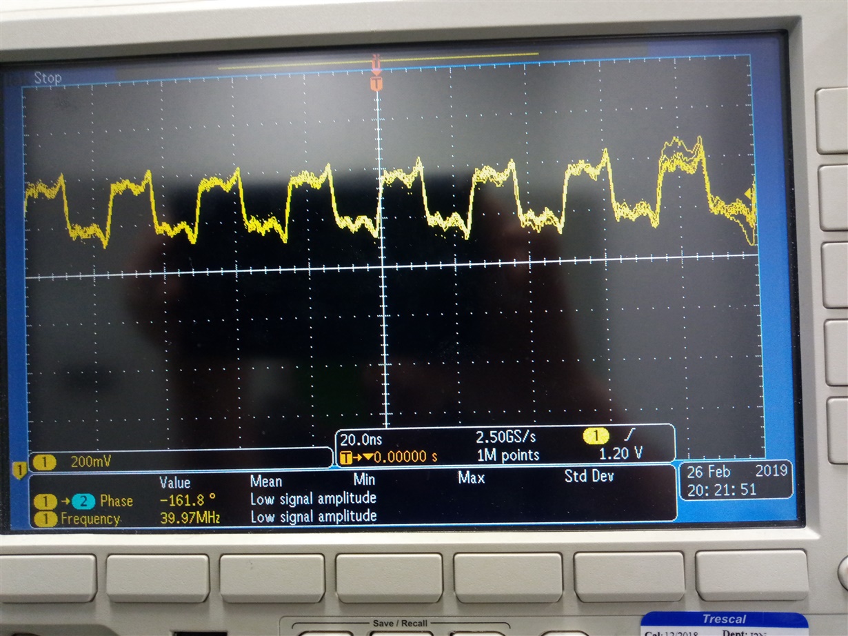
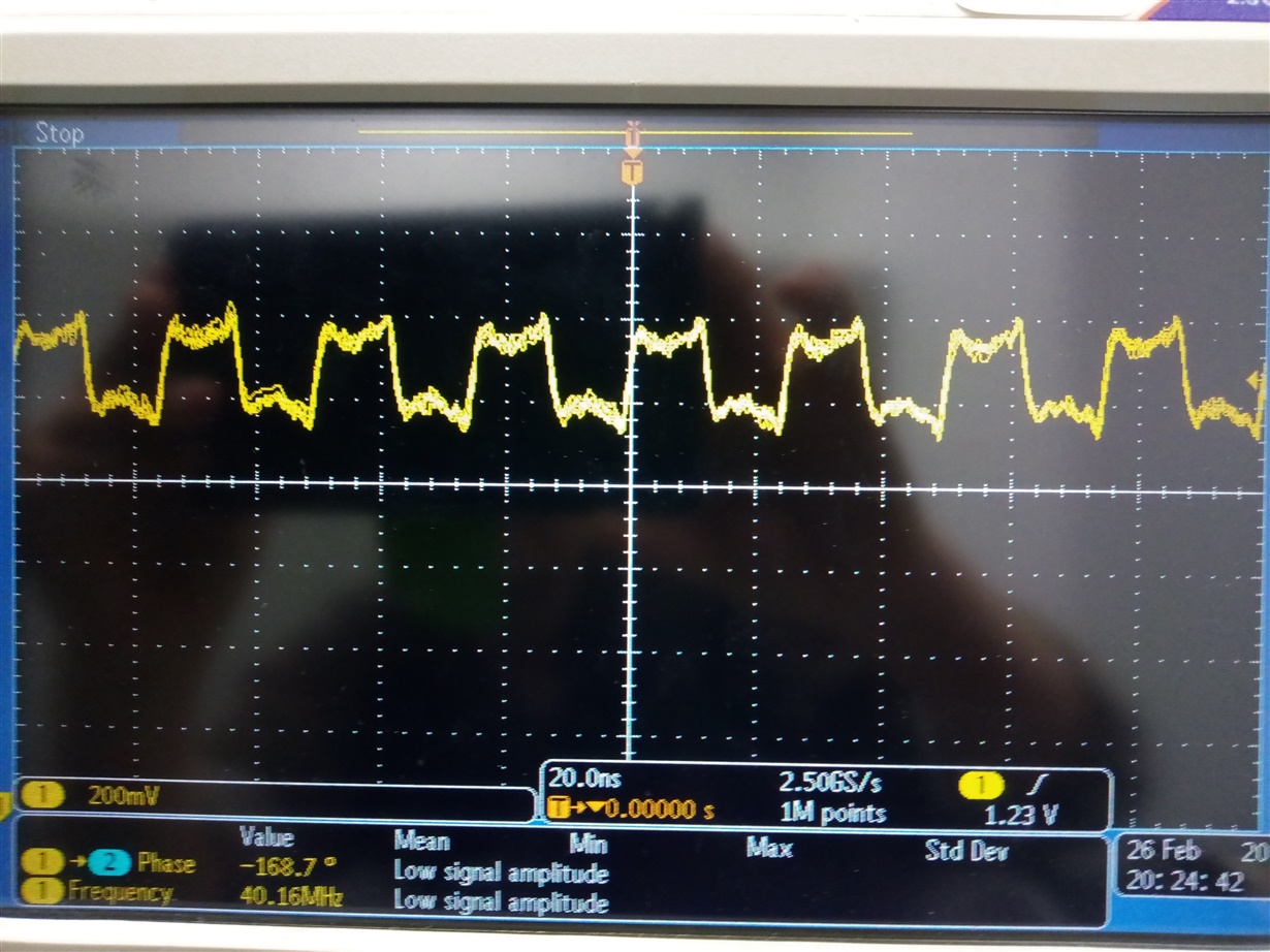
    We did the tests (one is using Custom Pattern 0x777, the other one is using Customer Pattern 0xFFF)

    but both Frame Clock signals (40MHz) look similar, not much different.

    1) Custom Pattern 0x777

    2) Custom Pattern 0xFFF

    Thank you!

    Best regards,

    Chen

  • Hi Henry,

    How are you?

    Since the AFE5808A output are LVDS signals,

    it needs to follow the AFE5808A's data sheet as:

    The output signal offset should be around 1.1V range.

    and each output signal is about 200mVpp (showing you from our scope capture)

    (So the differential signals are about 400mVpp).

    So please double check these hardware settings on your FPGA data capture side.

    Thank you!

    Best regards,

    Chen