This thread has been locked.

If you have a related question, please click the "Ask a related question" button in the top right corner. The newly created question will be automatically linked to this question.

DAC161S997: Doubts in the 4 to 20 mA current loop transmitter reference design - TIDUAM6

Part Number: DAC161S997

Hi Team.

Please address the following questions:-

1. I referred "4-20 mA current loop transmitter reference design - TIDUAM6". Refer page 16,17/27 of the document. Equation 6 in the description below says Iout = Iin + Ir21 + Ir22 whereas I believe it has to be Iout = Iin = Ir21 + Ir22. Please do explain if something is wrong at my end.

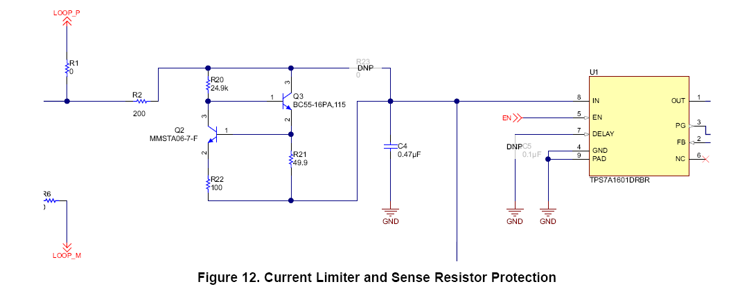
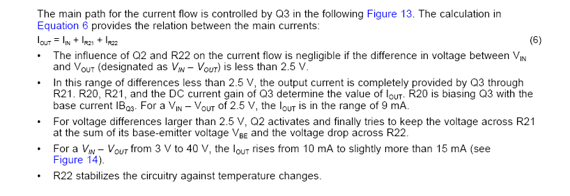
2. Can you please elaborate me the description below figure 12 of the document. How 2.5 V came out as a reference value and why not some other value ?


Regards.

  • Hi Nitin,

    1. You are correct. All of the current flowing into the input makes up Iout.

    2. This is not an exact value but basically because 2.5V/250 = 10mA, and 10mA*49.9ohm = .5V which is less than the required Vbe to turn on Q2. So at a difference of 2.5V all of the current will flow through Q3. This could be considered the maximum normal operating current.

    The way this circuit works is that the current flows through Q3 as the Vbe is veryhigh when the current is not being limited. At a certain point when the voltage across R21 is 0.6V-0.7V Q2 will turn on and start to pull down the base of Q3. Of course it is not either on or off when this occurs, but reaches an operating point limiting the current at an approximate value, Vbe/R21 = 0.7V/49.9 = 14mA. The exact current limit will depend on the properties of the BJTs.

    Thanks,
    Garrett
  • Hi Garrett,

    Thank you for the details.
    I shall work on it and come back to you for any future queries.

    Good day.
  • Hi Garrett,

    1. Can you please elaborate me the exact reason for implementation of the transistor at BASE pin of DAC161S997 IC ?

    Regards.
  • Hi nitin,

    The transistor at the BASE pin is controlled by the internal amplifier to regulate the loop current value. The current flowing through this transistor is the 'additional current' required to reach the desired loop current value. So if the on-board circuitry required 1mA for operation and the loop current was set to 4mA, 3mA would flow through this path to make up the total.

    Thank,
    Garrett