This thread has been locked.

If you have a related question, please click the "Ask a related question" button in the top right corner. The newly created question will be automatically linked to this question.

ADS1220: help with interfacing to three wire thermistor circuit

Part Number: ADS1220

Hello, 

I am attempting to use the ADS1220 analog to digital converter with a temperature sensor cable (model 107) that I have purchased from Campbell Scientific. The sensor uses a 100K6A1iA thermistor. This thermistor has a fairly high resistance for my application's temperature range. Below is the min and max temperature for my application and the associated thermistor resistance values.

10 Celcius -> 207801 ohms

28 Celcius -> 87027 ohms

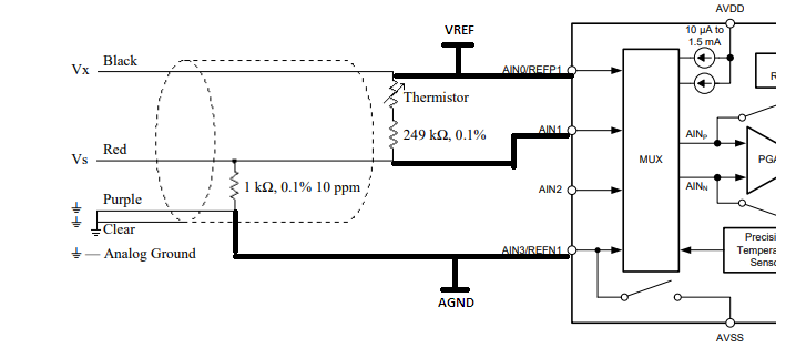
Below is a wiring diagram of the cable which has three leads. The 249K ohm resistor shown in series with the thermistor is for linearization. The manufacturer intends for a voltage reference to be connected at 'Vx' and then the 'Vs' voltage is measured. Then the 'Rs' value of the thermistor can be calculated if the 'Vx' and 'V's are both known. Then using the Steinhart & Hart equation the thermistor temperature can be calculated.  

After reviewing the datasheet for the ADS1220 ADC its not completely clear to me the proper way to interface my 107 temperature probe to this part. Within the datasheet there are application schematics showing 2,3 and 4 wire RTD connections however I am not sure if these are applicable to the configuration of my 107 temperature probe.

Perhaps I could use one channel on the ADS1220 to measure the 'Vs' voltage and a second channel to measure the 'Vx' voltage. Alternatively I could potentially use an external voltage reference to drive 'Vx' and connect this point to the input voltage reference for the ADS1220. Then I should only need to measure the voltage at 'Vs' using the ADS1220 part. I don't believe the ADS1220 part makes the internally generated 2.048V reference available to a pin on the IC? If this reference voltage were available externally to the ADS1220 then I could use it as the 'Vx' voltage in my application.  

I appreciate any information and guidance on how I may be able to use the ADS1220 part to measure the thermistor value in the 107 sensor cable. 

Sincerely, 

Sean McPeak

  • Hi Sean,

    Welcome to the E2E forum!  I would suggest that you make the measurement ratiometric by using the same excitation source to also be the ADS1220 reference.  One way of doing this is to use the AVDD supply as the reference (or you could use a totally separate reference voltage if you wish as long as the voltage is less than or equal to AVDD) and connect this to the ADS1220 AIN0/REFP1 input.  The Black wire should also connect to this same input.  The Red wire should connect to the AIN1 input of the ADS1220, and the Purple wire should connect to the AIN3/REFN1 input.  The AIN3/REFN1 should also connect to AGND (AVSS).

    You would need to make the register settings for the ADS1220 to use the REF1 reference input and select the measurement to use the input AIN1/AVSS with PGA disabled and bypassed.  You can use up to a gain up to 4 with the PGA bypassed, but I would start with PGA of 1.  Configuration register 0 = 0x91 and Configuration register 2 = 0x80.

    As the measurement is ratiometric, instead of using the voltage ratio that was given in the 107 datasheet, replace the ratio with codes relative to positive full-scale.

    Conversion code / 2^23 = 1000 / (Rs + 249k +1k)

    Solving for Rs (thermistor resistance) Rs = ((2^23 *1000) / Conversion code) - 250k

    Best regards,

    Bob B

  • Hi Bob,
    Thank you very much for your detailed response and suggestions. The configuration you outlined with the ADS1220 and 107 temperature probe make good sense to me
    and I agree with your suggestion to start with the PGA set to 1. Since you suggested configuring the ADS1220 for using an external reference I am assuming that the part's
    internally generated reference is not available on a pin for connection to the circuit?
    My main concern with using the 107 probe is the high resistance value of the thermistor along with the series linearization resistor which both contribute to a good amount
    of signal attenuation. This morning I found a slightly different temperature probe (109) made by Campbell Scientific and I think this may be a better solution for my application.
    There are two advantages that I see to the 109 v.s. the 107 for my application.
    1. There is no linearization resistor in series with the thermistor. So less attenuation to deal with. Since I will be using the Steinhart & Hart equation with the
        fitted coefficients I don't think I should need any linearization in the circuit.
    2. The thermistor used in the 109 probe has significantly lower resistance values then the thermistor implemented in the 107 probe.
        This should allow for a greater 'Vs' voltage swing for a given excitation voltage or current source.
        For the 109 probe the Rs = 19903 ohms at 10C and Rs = 8777 ohms at 25C.
    For my application the cable length will be ~ 100 feet which has me concerned about noise. For that reason I think I might want to consider driving the probe with a constant current source
    v.s. a voltage reference for improved noise immunity. If I was to use a constant current source to drive the 109 probe could I then use the ADS1220 part's internally generated reference
    to measure the voltage developed across the 24.9 Kohm resistor (as long as the total voltage span was < Vref)? Alternatively I could use an external reference as you outlined in your earlier post.
    Below is the schematic for the Campbell Scientific 109 temperature probe that I am considering using instead of the 107.
    Thank you again for your input and help.

    -Sean M

    image.png

  • Hi Sean,

    Unfortunately there is no reference output for the ADS1220, however with the lower resistance probe you could use the IDAC to develop required excitation as long as you stay within the IDAC compliance voltage. You should be able to do this at the 50uA setting. This would be more similar now to an RTD measurement as shown in the applications section of the datasheet.

    In this case I would alter the inputs slightly while still keeping the measurement ratiometric. Instead of measuring across the 24.9k resistor, you would use this resistor as the reference voltage. Connect the Red wire to REFP0 and AIN1. Connect the Purple wire to REFN0 and AGND (AVSS). The Black wire would connect to AIN0 and the measurement would be AIN0/AIN1. As the measurement is now off from AGND, you can leave the PGA enabled for higher input impedance for the measurement. I would also add some series resistance (1-2k) and a differential cap (10-100nF) across the inputs to provide a low-pass antialiasing filter. You could also add common-mode filters, but the cap value should be 1/10 or less than the value of the differential cap to remove the effects of drift from the filters creating a difference voltage.

    The excitation current can come from AIN2 or AIN3 and this should connect directly to the Black cable and not go through the filter resistor.

    When the cables are very long, you need to be very careful with cable shield termination so that it is properly terminated.

    Best regards,
    Bob B
  • Thank you Bob. Below is the proposed schematic for interfacing with the 109 thermistor probe as I understand it based on your recommendations.

    I have a few questions below if you don't mind.

    1. Would the AIN0/AIN1 measurement be a differential type across the thermistor directly?

    2. The reference voltage you described would now be across the 24.9K ohm to GND and I believe would vary as the thermistor resistance changes.

         But this must be OK since I believe the measurement would be differential across the thermistor?

    3. Is it fair to say that using the current source approach has greater noise immunity for long cable runs v.s. a voltage source approach?

    thank you.

    -Sean M

  • Hi Sean,

    Your block diagram looks correct.  You may want to add a similar reference filter as you have for the analog input.  See my additional comments below.

    Best regards,

    Bob B

    Sean McPeak said:

    Thank you Bob. Below is the proposed schematic for interfacing with the 109 thermistor probe as I understand it based on your recommendations.

    I have a few questions below if you don't mind.

    1. Would the AIN0/AIN1 measurement be a differential type across the thermistor directly? [BB] Yes, you would measure the thermistor directly as a differential measurement.

    2. The reference voltage you described would now be across the 24.9K ohm to GND and I believe would vary as the thermistor resistance changes.

         But this must be OK since I believe the measurement would be differential across the thermistor? [BB] As you are now using a constant current source, the voltage across the 24.9k resistor should remain relatively constant (except for resistor drift).  The drift characteristics for the 24.9k resistor would be the same whether you voltage excite or current excite.  The advantage of the current excitation and ratiometric measurement is if the excitation drifts there is no direct relationship to conversion result.  In the end you end up with a ratio for Rs/24.9k = Code/+full-scale.  This is due to the IDAC source being the same for the reference and the thermistor, and the IDAC term drops out of the measurement.

    3. Is it fair to say that using the current source approach has greater noise immunity for long cable runs v.s. a voltage source approach?  [BB] Your noise immunity is going to be a bigger issue relative to the termination of the cable shield.  In this particular case the current through the sensor path using voltage excitation will be pretty much the same as with the current source.  I long cable run will add some resistance which also adds a voltage drop across the wiring.  But this should pretty much cancel out with either excitation method due to the sizing of the components.

    thank you.

    -Sean M

  • Thank you Bob. I updated and posted my block diagram to hopefully show the addition of the common mode filters that you suggested as well as the reference filter that you recommended.

    That makes perfect sense what you said regarding the Vref staying constant due to the 50uA constant current source through the 24.9Kohm resistor. I wasn't thinking about that correctly in my previous post.

    I see the benefit you mention regarding the usage of the constant current source as well along with the ratiometric measurement and using the voltage across the 24.9 Kohm as Vref for the A2D. As you said the current cancels out in the ratio leaving:
    Rs/24.9K = Code Measured / +Full Scale Code

    For my application I think I should also plan on using the 50/60 Hz filters within the ADS1220.

    -Sean M
  • Hi Sean,

    Similar to what you have done for the analog inputs, I would further suggest adding an RC low-pass filter to the reference inputs. Otherwise I think you have it pretty well figured out.

    Best regards,
    Bob B
  • Hi Bob,

    Thank you again and I will be sure to add the RC low-pass filer to the reference input REFP0 as you recommended.

    I appreciate your help with my application and usage of the ADS1220 part.

    -Sean M

  • Hi Bob,

    In section 8.5.2 of the ADS1220 user manual there is a description of the 24 bit binary twos compliment data output from the device. I attempted to calculate the expected resolution with my application and wanted to ask if you agreed with my results if you don't mind.

    For my application using the 50uA current source my Vref to the ADS1220 should be 1.245V. This is based on 50uA through the 24.9K ohm fixed resistor in the 109 thermistor probe. Based on equation 16 in the data sheet (and assuming a gain of 1 for starters) I calculate a resolution of 1.484 X10^-7 Volts/count.

    With 50uA of drive current my differential thermistor voltage should vary from 0.99515V @ 10 degrees C and then 0.43885V @ 28 degrees C. This equates to a deltaV of 0.5563V which I think would result in a span of 3748259 counts.

    Than you and I appreciate your input.

    -Sean M
  • Hi Sean,

    You are correct if there were no noise involved in the conversion process. In Table 1 of the ADS1220 datasheet on page 16 you will notice there is typically 13.67uVpp of noise at a gain of 1 at 20sps. Using the calculation in equation 2 on the same page, the number of noise-free bits comes out to about 17.47 bits. This will exclude any noise external to the device (such as EMI/RFI). This will alter the result so that 1 code is now 13.43uV. You span counts would now lower to 41422 counts. This is your best case scenario.

    Best regards,
    Bob B
  • Hi Bob,

    I understand what you saying regarding how the noise effects the conversion process and reduces the number of bits of resolution. I see where you got the 13.67uVpp from table 1 on page 16 in the datasheet and I calculated the same 17.47 bits based on equation 2. However I noticed that table 1 mentions that the internal reference is set to 2.048V. For my application I plan on using an external reference which will be 1.245V (50uA x 24.9K). Based on equation (3) on page 16 this should give me a full scale range of 2.49V. Will this have an effect on the uVpp noise when the gain is 1 and 20 SPS?

    I also am not sure I follow how you arrived at 13.43uV per count or the total 41422 counts? If I take 2^17.47 I get 181549 counts. Then (2 x 1.245V) / 181549 counts = 13.715uV / count. So I don't get the same result for V/count or number of counts.

    Thank you again.

    -Sean

  • Hi Sean,

    The calculation is a best case scenario with shorted inputs. Most likely you will not achieve this with a sensor connected, but prior to connecting the sensor you should see something close to this value if you short the device inputs. This will give you a baseline starting point. We don't have a table for a lower reference voltage, but the noise within the ADC will be about the same anyway as the reference is more or less taken out of the measurement as the input is shorted.

    You calculation appears to be correct. I must have copied or typed something incorrectly in my previous post.

    Best regards,
    Bob B
  • Thank you Bob. I understand what you are saying regarding the fact that I won't achieve the calculated best case resolution with the sensor applied. I appreciate your help with my application and usage of the ADS1220 part.
    -Sean