This thread has been locked.

If you have a related question, please click the "Ask a related question" button in the top right corner. The newly created question will be automatically linked to this question.

ADS1262: Real data rate of ADS1262

Part Number: ADS1262


Hello

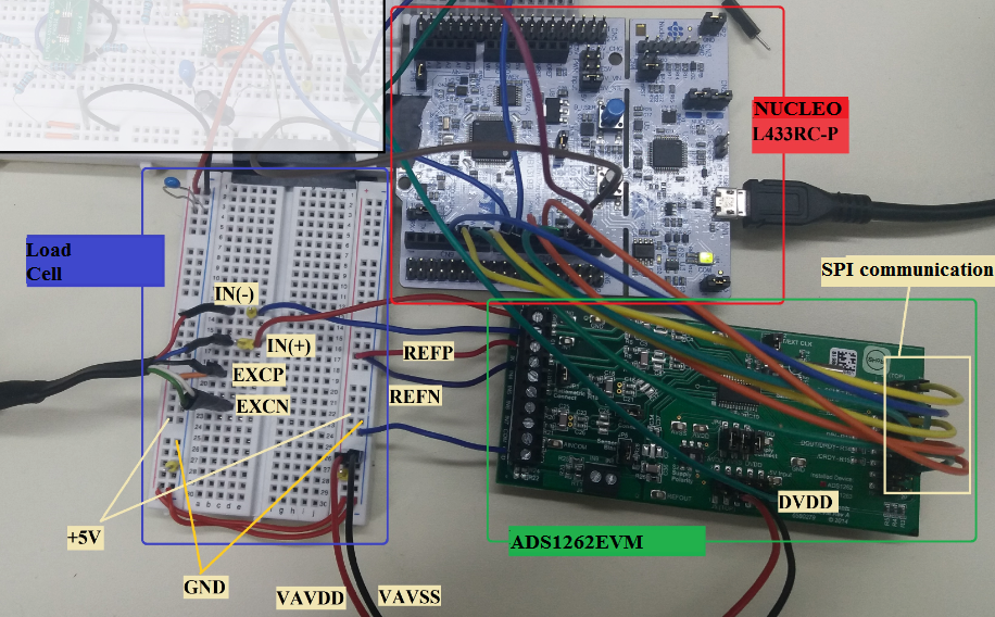
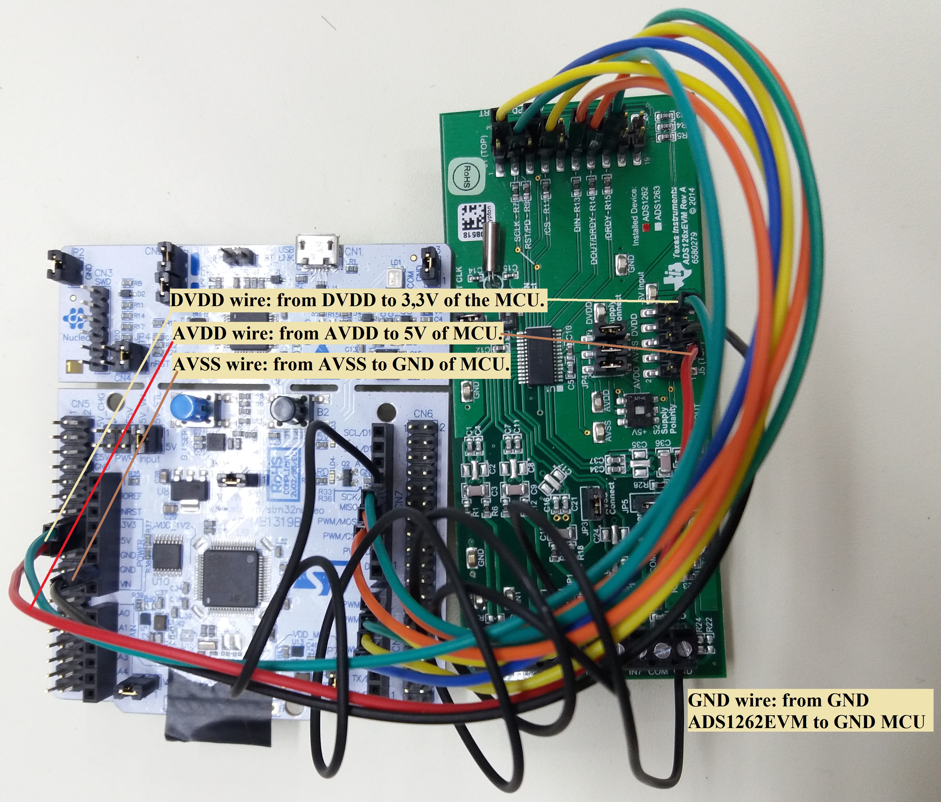
I´m using the ADS1262EVM to take measures of a load cell.  I wanted to measure the real frequency at I was working and for that I measured the time that the ADC take in doing one conversion depending of the different frequencies of work (programming the MODE2 register).

Between 2.5 SPS and 400 SPS it was obtained a constant and equal value of time for all the measures, and the value of time was correspond to the programming frequency (f=1/t).

But from 400 SPS to 38400 SPS the values for each measure of time was different and seem as if they follow a system.

I insert a excel file with the collect data to see it better. The measure of times are in seconds (s).

I would like to know if it is normal or it is because this ADS1262 chip have some problem and works bad for this frequencies. And if it is normal the reasons of these responses of frequency.

Thanks in advance.

Best regards.

3568.TEST of times.xlsx

  • Hi,

    Have you tried monitoring the /DRDY pin on an oscilloscope, or how are you measuring the time between conversions?
    If you look at an oscilloscope you should see that the time between /DRDY falling edges is consistent with the programmed data rate.

    If you're able to share your other register settings and perhaps a code snippet of how you are reading data it might help me see what the possible issue might be. There are other modes (pulse convert, SINC2/3/4/5, chop, and the programmable conversion start delay) which may be affecting the output data rate.

    One possibility is that the /DRDY pin is pulsing at the correct rate, but the MCU may be busy and not handling the /DRDY interrupt fast enough, leading to a loss of data.
  • I measure the time with a timer using the MCU.

    I´m working with continuous conversion mode, a gain of 32 V/V, a sinc 4, chop disable and I don´t use delay.

    Here you have some parts of my code:

    The configuration of the registers:


    The function with which I read the data:


    ****The start command is sending in the initialization.

    And the conversion_dato() function:

    Thanks.

    Best regards.

  • I would try commenting out the following lines of code and just return dummy data...

    AdcOutput=(double)conversion_dato();
    AdcOutput_mV=((resolution)*AdcOutput)*1000.0;

    Currently, the code is polling /DRDY and then goes off to read the data. While the MCU is reading the data it will not be checking the state of /DRDY and so it could be missing these signals and causing the data rate measurement to be incorrect.

    Also, what frequency is your SCLK? A slow SCLK might be the reason for why reading the data is taking a long time.

  • Hello

    I´m using the crystal oscillator of the ADS1262EVM and its nominal frequency is 7.3728 MHz.

    I have measured the /DRDY pin with the oscilloscope and its response is correct and correspond with the programming data rate. But I have seen three cases:

    1.- For low frequencies the /DRDY pin show perfect and the data is retrieval (as it is said in the pag. 67 of datasheet). All work good.

    2.- When the frequency is increased for example to 7200 SPS, the data is not retrieval. I would like to know why happens this and how I can put a solution.

    3.- When I use a frequency of 100 SPS for example and I measure the time with a timer, I obten an incorrect value of time that correspond with a samplig rate to 400 SPS. But at the same time, the signal of /DRDY pin measured with the oscilloscope is correct and correspond with the 100 SPS. Why happen this if in the code I´m using the "while" to wait until the data is ready?

    Thank you 

    Best regards.

  • What MCU are you using and are you jumper wiring this MCU to the ADS1262EVM?
    If so, would to be able to share picture of your hardware setup?

    Do you have the ability to use a /DRDY interrupt instead of polling the /DRDY pin?
    Likely you'd be able to control the timer with much more precision within an interrupt. Why the timer shows a data rate faster than 100 SPS doesn't make much sense, I'd expect it to show a slower data rate unless there is some configuration issue or false triggering of the timer.

    Would you also be able to share what the "ADS1262_DRDY_PIN" macro is doing?
    Perhaps something about this macro is not working as expected.
  • Hello

    I´m using the MCU L433RC-P of STMicroelectronics. And it works at a frequency of 33 MHz.

    Here you have the connection with the ADS1262EVM:

    -Do you have the ability to use a /DRDY interrupt instead of polling the /DRDY pin?

    I have tried to do this on this way:

    Where waitDRDY() is:

    On the falling edge of /DRDY pin the function ``pinDRDY´´ is executed.

    Doing this the problem at high frequencies persists, and when I measure the /DRDY pin with the oscilloscope it shows that the data is not retrieval.

    - Would you also be able to share what the "ADS1262_DRDY_PIN" macro is doing?

    The "ADS1262_DRDY_PIN" is a Digital Input declared in the SPI class.

    And it is used when I want to read a data in this way:

    Thank you 

    Best regards.

  • Hi José,

    At the moment it would seem like the MCU is not reading the data fast enough above 100 SPS and causing your timer to return a bad result.

    Is the interrupt code that you showed above working at the lower data rates? Technically you're just polling for the interrupt now, but this should be faster than polling the GPIO pin, so I still prefer this implementation as long as it works.

    With the four different boards your jumper wiring between you can run into a lot of issue with poor signal integrity and ground bounce. For debugging, can you remove the two bread boards and just connect the NUCLEO board to the ADS1262EVM? Make sure to have a ground wire connected between these two boards, and if you can, wrap this ground wire around all of the other wires going between these two boards so as to minimize the loop area/distance between these wires.

    I recommend starting from a simple test setup. Select the analog supplies of the ADS1262 as the reference source and short the ADC inputs to AINCOM (internally) with VBIAS enabled. If you can get this setup to work and verify that the noise performance looks good, then I'd recommend adding in the load cell and testing the noise with the load cell connected. Also, you should be able to connect the load cell directly to the ADS1262EVM and remove the intermediate bread board. Doing should should help remove one possible error source.
  • Hello

    - Is the interrupt code that you showed above working at the lower data rates?


    Yes, it works at the lower data rates. It works similar to polling the GPIO. When the programming data rate is bigger to 20 SPS start to appears problems. For example for 50SPS the measure time correspond to 79 Hz, to 60 Hz with 107 Hz, to 100 Hz with 379Hz and from then the rest of the frequencies give different times for each measurement.

    - Do you refer to try with this configuration?


    I´m going to try, but I think that the problem should be in the programation and not in the signal noise.

    Thank you, I appreciate your help.

    Best regards.

  • Hi José,

    That's the right idea but minimize the loop area as much as possible, especially with regards to the area between the GND and SCLK wires.

    Here is an example of what I typically do:

    Notice the ground pin adjacent to SCLK. Connecting the ground wire to this pin will help to avoid digital signal integrity issues:

    It's possible that your issue is purely code related, in which case you ought to be able to debug it with this setup. I would highly recommend trying to solve this problem with a simplified setup before putting everything back together. When trying to debug a system as a whole it often becomes very difficult to track down the source of the issue, whereas building upon a working sub-system and testing new additions will better allow you to figure out where any issues might lie.

    Best regards,
    Chris