Dear TI,
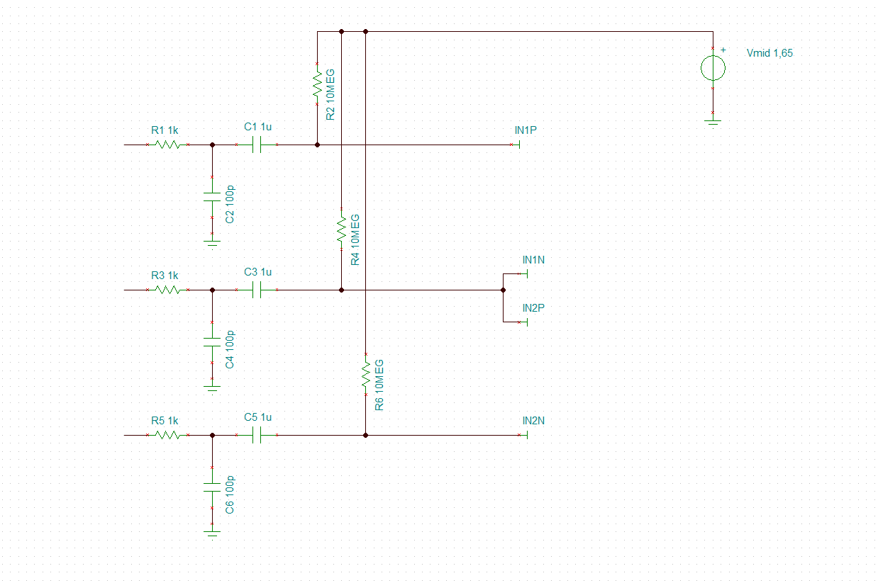
This question is asked a number of times already on this forum. The advice is to go for an AC coupled design and DC bias the input terminals to the mid supply voltage. The DC bias can be done by:
- a voltage divider e.g. 2 resistors of 10M between Vss and Vdd
- using the output RLD amplifier as a unity gain buffer and configure the input of the RLD amplifier to the mid supply and use a large resistor to pull the inputs of the ADS1292 to the mid supply
I am wondering why AC coupling is advised with respect to reducing common mode problems, because the to be expected common mode problems are from capacitive coupling of the mains (50 / 60Hz) grid and the high pass filter that forms the AC coupling will just let these frequencies pass. They hopefully will be sufficiently rejected when the CM components at the input terminals are subtracted from each other (made differential).
The whole idea of 24-bit dynamic range from what I understand is to be able to cope with large electrode offsets (+-300mV) and the CM mode components on the terminals and still be able to sufficiently quantise the relative small (2mV) ECG signal.
I understand of course that if you would use DC coupling some form of high pass filtering would be required to remove base-line drift of the ECG signal but this could be done digital that does not necessarily has to be done by AC coupling.
Can you shed some light on this? I am sure it will be valued by many users that want to build an application were the use of an RLD electrode is not possible.
TIA for your support