This thread has been locked.

If you have a related question, please click the "Ask a related question" button in the top right corner. The newly created question will be automatically linked to this question.

ADS1292: how to cancel the 50/60Hz noise without RLD lead

Part Number: ADS1292

Dear TI

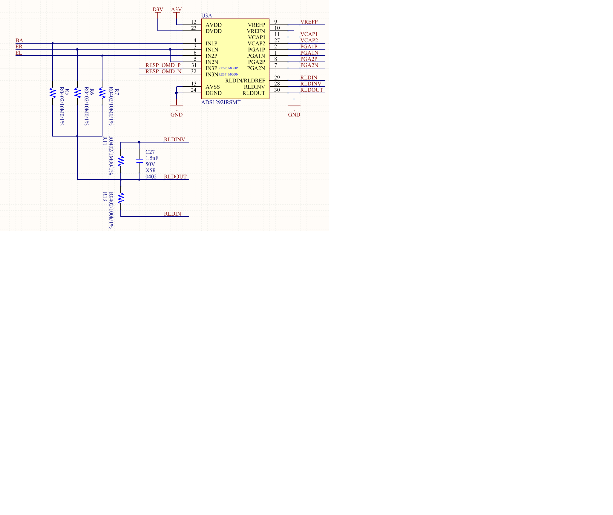
My circuit is with only 3 leads BA,ER,EL. Therefore i don't have the lead to connected to RLDOUT.

How should I improve the rejection of 50/60Hz noise.

Will my design bellowed will work?

And the input impedance reduces to 20M, is there any good solution?

  • Hi Harvey,

    Thank you for your post and welcome to our forum!

    The circuit you are showing will work ok for measurements without an RLD electrode, but you will not see the same improvement in CMR in this setup. As you can see in this application note, the lower the resistance between the RLD output and the body, the better the common-mode cancellation effect is.

    The other concern with this approach is the reduced input impedance. For IEC/AAMI standards, you will probably need greater than 10 M in order to limit the DC current. Larger resistance values may lead to significant offset in the presence of leakage current. You can try increasing the resistors to 100 M and reduce the gain of the PGA to see if you can meausre the inputs without saturating the amplifier.

    Best regards,

  • Dear Andrews

    So, increasing the resistor is better for input impedance but worse for CMRR?

    Another question :

    In other issues opened in this forum for no RLD lead, you suggest that driving IN1N, IN1P, IN2N, IN2P to VDD/2 with ac coupling.

    I want to know if the RLD_SENS is set as 0x2f is better than 0x20
  • I may be able to tell something about it. But I have a few questions:
    -What is the purpose R11 and C27?
    -What is the purpose of R13?
    -Is the ADS1292 set-up such that RLD out is at mid-supply?
    -Do you intend to design a battery operated device?
  • Setting RLD_SENS to 0x2F means that common mode signal of the 3 input leads in your schematic are inputs for the inverting RLD amplifier and that this signal is fed back to the leads again via the 10M resistors, I don't think that will work.
  • Hi Harvey,

    I'm not sure if RLD_SENS = 0x2F will work either, it may simply cancel out your signal of interest. Typically, the RLD is used for common-mode cancellation when there is some separation between the placement of the RLD electrode and the ECG measurement electrodes (RA, LA, LL, etc.).

    Chief - R11 and C27 set the closed-loop bandwidth of the RLD amplifier. Limiting the bandwidth helps maintain stability as the RLD amplifier is driving several high-frequency poles from cable parasitics, etc, which are part of the larger feedback loop that encompases the patient.

    R13 is the protection resistor used if RLD is routed back into the chip and drives the patient through one of the measurement electrodes. See "Rerouting the Right Leg Drive Signal" section on page 50. If this feature is not used, R13 can be left uninstalled.

    Best regards,

  • Hi Ryan, If the RLD amplifier is used in a configuration to drive an RLD electrode I understand the purpose of R11 and C27 but the idea in this thread is not to use an RLD electrode. So in this case I would expect the RLD amplifier to be configured as unity gain buffer, so RLDOUT and RLDINV shorted and no R11 and C27. The RLDREF_INT bit is set to 1 meaning that RLDOUT is at mid suply and used to bias the leads via the 10M resistors. Since the inputs are already pulled to the mid supply I see no use for R13 in this application.

    Kind regards,
  • Hi Ryan
    Thanks for your reply, I will try the different configuration and measure the signal.
  • Ah yes, my mistake. In that case, I agree with your reasoning.
  • So, does it mean that unity gain is better?

  • Hi Harvey,

    I would recommend leaving the RLD circuit as it is for now with the closed-loop feedback components installed. Even if you are just driving a DC voltage to set the common-mode, the closed-loop bandwidth will limit some of the RLD amplifier noise. It will not hurt performance to keep them.

    I have some preliminary simulation results that indicate the RLD amplifier can still be used to mitigate some of the CMR loss due to antialiasing filter mismatch (fyi - the antialiasing filters are not shown in your schematic). However, because we are not driving the body directly, any common-mode-to-differential signal conversion that occurs before the RLD pull-up will not be reduced by this method.

    I'm not totally sure yet whether AC-coupling is more helpful or hurtful in this configuration. I'm continuing to look into that as well.

    Regards,
  • "he closed-loop bandwidth will limit some of the RLD amplifier noise"    ->  I tend to disagree, although not significant, noise will increase by the 1M feedback resistor that is shorted by the 1.5n capacitor for high frequencies. 

    noise simulation with open switch:

    with closed switch:

    Simulation confirms this. So you add components and make things worse. I do not see the benefit.

    Kind regards

  • "I have some preliminary simulation results that indicate the RLD amplifier can still be used to mitigate some of the CMR loss due to antialiasing filter mismatch (fyi - the antialiasing filters are not shown in your schematic)." -> from the datasheet I understand you get a CMRR typically of -120dB @50/60 Hz unless you create imbalance by poor layout of the differential filter capacitor.

    I also want to point out that imho that 50/60Hz common mode noise is mainly an issue if the amplitude of this signal is getting out of the common mode input range. For the example in the datasheet VDD= 3 V,gain= 6,and VMAX_DIFF= 350mV (typically electrode-skin contact DC, plus a few mV from the ECG signal itself) that would be 1.5±0.25V. So if the 50/60Hz CM amplitude is below 250mV under these conditions with a CMRR of -120dB that would be smaller than 0.25uV on an ECG signal of a few mV no issue at all.
    So reducing 50/60Hz problems is not a matter of super low CMMR suppose we have only -108dB than we would get 1uV on a signal of a few mV ECG so what. Trouble starts when we get out of the CM input range because the amplifier can saturate. Without driven RL the only way to influence that is very good isolation wrt CM noise source ground.

    Kind regards

  • Dear Chief

    In IEC 60601-2-47, we should test the CMRR through imbalanced impedance. The rejection is still a major issue.
    And I think the entire closed-loop is "RLDOUT-patient-PGA1P-RLDAmp". When the loop gain get higher the closed-loop gain get lower, but in the meanwhile phase margin and gain margin will decrease. en.wikipedia.org/.../Control_theory
    In this case, decreasing the high frequency could improve the noise rejection.
  • Hi Harvey,

    The idea is to use the RLD just as a buffer for the the internal Vmid (AVDD+AVSS)/2 of the ADS1292. So the loop  "RLDOUT-patient-PGA1P-RLDAmp" you are talking about is another concept, which I do not understand. Maybe you can explain.

    Yes, I know, it is the most challenging test in the standard. But the CMMR in this test, is not the CMMR of an amplifier (even if the amplifier has a CMMR of -300dB it would not help you). The essence of the test is shown in the included figure. The applied imbalance will lead to a differential voltage. You have to ask yourself how you can minimize this voltage. If the recorded voltage is larger than 4mVp the test will fail. That is why 60 dB is specified:  20log(4/4mv)=60.

    Kind regards,

  • YOU may use digital notch filter or digital integrator, with reset, running on cpu core,which has reset period 1/60Hz or 1/50Hz