Hi,
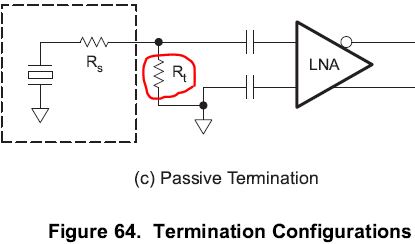
We are experiencing problems with signal distortion when sampling "low frequency" signals in TGC mode with our own prototype hardware. We enable the LNA HPF (200 kHz cut-off) and PGA HPF. INP is ac-coupled with 15 nF and INM bypass is 15 nF. We don't use any active termination, but we do ac-couple the active termination pin with 1 uF so we can take advantage of the input voltage clamp function.
Injecting a 30 kHz CW test signal above a certain amplitude the sampled signal starts to run away in amplitude and distort (multiple harmonics appear). The signal measured at the AFE INP with oscilloscope is a clean sinusoid however, so there seems to be something going on inside the AFE. Disabling the LNA HPF and PGA HPF seems so "solve" the problem, but then we lose valuable ADC range due to the non-zero DC level.
It seems to us that most likely the HPF / DC-compensation circuits are causing problems. Increasing the bypass capacitor at INM from 15 nF to 1 uF didn't help by the way.
In more detail the AFE is initialized as in the datasheet power sequence including a hard reset, then the following registers are programmed:
0x000001 (soft reset)
0x010014 (must write)
0x032000 (14 bit lvds)
0x040011 (MSB first, 14 bit adc)
0x430000 (no clock skew)
0xc30018 (PGA HPF off, LPF 10 MHz)
0xc41000 (LNA HPF off)
0x150000 (HPF off),
0x020080 (sync pattern)
Here there is some LVDS timing/synchronization against the test pattern happening in our FPGA...
0x020000 (normal sampling)
0x000000 (ADD_OFFSET = 0)
0xc30008 (24 dB PGA, enable PGA HPF, 10 MHz LPF)
0xc4c200 (individual LNA gain, LNA HPF, 1.5 Vpp input clamp, no active term.)
0xc50200 (low noise and noise figure mode)
0xc60200 (DIS_CW_AMP=1, TGC mode)
0xc9aaaa (all LNA 12 dB gain)
0xcb0088 (EN_DIG_TGC=1, 200 kHz LNA HPF)
0xcd0000 (PGA_CLAMP_HALF=0, SUPRESS_HIGHER_HARMONICS=0, V2I_CLAMP=0, RED_LNA_HPF_3X=0)
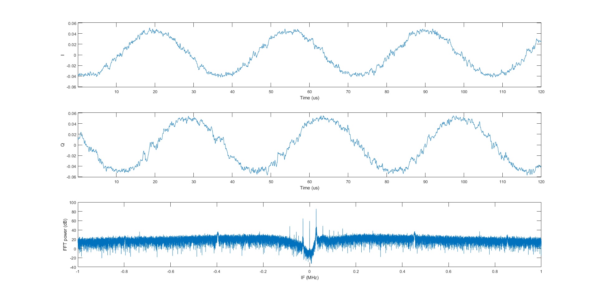
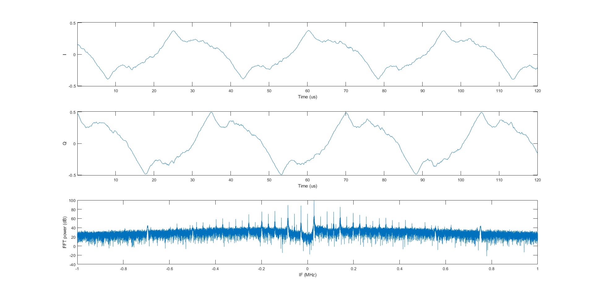
For a few different input levels we measure clean sinusoids of ~30 kHz with an oscilliscope at the AFE inputs, but what we observe in sampled data is shown in the below plots (where I = AFE ch 16, Q = AFE ch 15 shown for part of the sequence sampled, while the FFT is done on the complete sequence).
Input ~10 mVpp:

Input ~35 mVpp (some harmonic components are starting to show more clearly):

Input ~100 mVpp (here there is a clear jump in signal level and harmonic content):

Is there something we are doing wrong in the register programming or are there some limitations in the HPF/DC-compensation circuits that we have failed to understand?
Thank you,
Christer