This thread has been locked.

If you have a related question, please click the "Ask a related question" button in the top right corner. The newly created question will be automatically linked to this question.

ADS9224R: Reading and Writing Registers issue

Part Number: ADS9224R
Other Parts Discussed in Thread: AM5728,

I wanted to try programming registers on this part. I'm using a PRU core on an AM5728 to generate the SPI signals. However, I am not sure that I am doing this correctly.

I wanted to set register 5 (OUTPUT_DATA_WORD_CFG) to a value of 0x02 (enable fixed pattern in the output data word) and then read it back from the device.

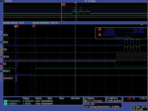
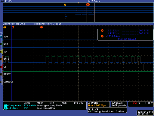
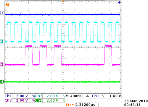
Here is how I reset the device (267ns low gong RESET pulse, CS and CONVST high incidentally):

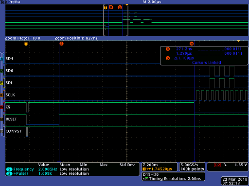
Then, I wait 1.1us before issuing and SPI communication:

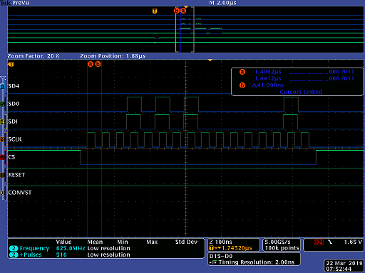
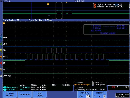
Then, I write to register 5 (send 0x1502 let me know if this looks ok). Notice how SD0 mirrors what I put into SDI.

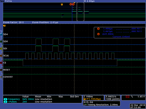
Then, I send command to read from register 5 (send 0x2500 let me know if this looks ok):

The datasheet says that the read results are returned in the next frame, so I send in (0x0000), expecting to see something returned on SD0 but 0 is seen on SD0.

Am I doing this wrong?

  • Hi Brian,

    Thank you for your post.

    The commands you're sending to the ADS9224R look correct for reading and writing registers. There seems to be a slight delay between the SCLK falling edges and the transitions on SDI, but the rising edges still align with the correct data value.

    However, I did not expect to see SDO mirror SDI like that. This may sound silly, but can you check if there's a short between them? Also, does SDO always mirror SDI like that, meaning you cannot even read default register contents or conversion data?

    Best regards,

  • Thank you for your suggestion.

    The SD0 line was run to the wrong pin on the chip and actually connected to SDI (my fault).

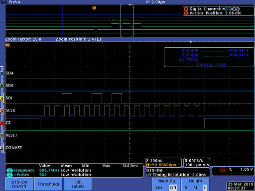
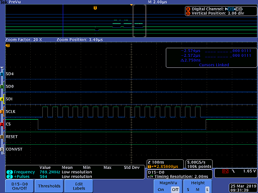
    This is how the signals look now.

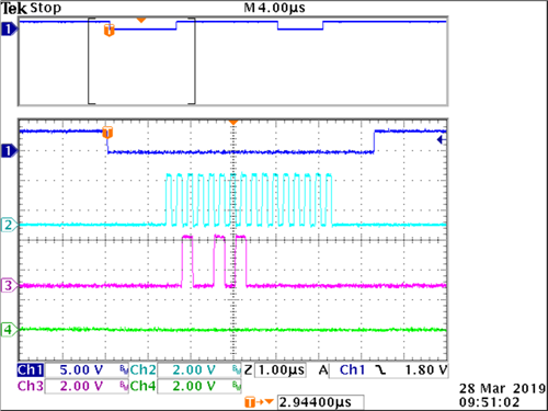
    Writing to register 5 (send 0x1502 let me know if this looks ok):

    Sending command to read from register 5 (send 0x2500 let me know if this looks ok):

    The datasheet says that the read results are returned in the next frame, so I send in (0x0000), expecting to see something returned on SD0 but 0 is seen on SD0.

    Let me know what you think. Am I doing this wrong?

  • Hi Brian,

    Thanks for the update. It still does not appear that you are misusing the device interface.

    I'm currently traveling, but I will return to the office on Wednesday this week. Let me see if I can replicate the same scope captures on the bench. Are you sending any other commands prior to writing to this register?

    Best regards,
  • I am not issuing any other commands prior to writing this register.

  • Hi Brian - thanks for clarifying. I will have the scope captures of the interface tomorrow morning.
  • Hi Brian,

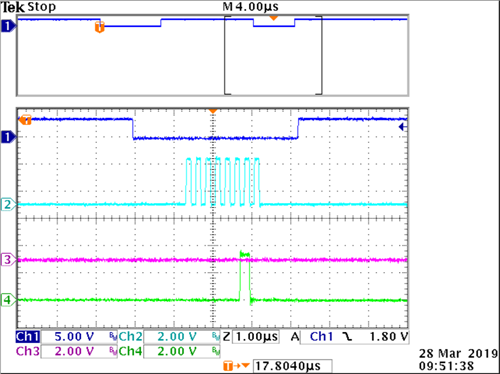
    Please see the following scope captures below:

    WREG 05h: 0x02


    RREG 05h:

    Register 05h value:


    Best regards,

  • I saw that your SCLK frequency was much lower. So, I tried lowering mine.

    10MHz did the trick. So, why does it need to be so slow?

    Datasheet says 60MHz for single data rate.

  • Hi Brian,

    I'm glad things are working now. At the moment, I can't tell for sure why the slower SCLK would have made a difference. There might have been some timing violation that was mitigated by slowing things down, but so far I don't see what that might be. The setup/hold times between SCLK rising edge and valid data on SDI are only 1.5 ns, which you seem to be meeting in all cases.

    You might want to double-check the time between /CS falling edge and first SCLK capture edge (tSU_CSCK). This needs to be a minimum of 12 ns. You certainly have enough time in the last image, but it might be a little close in the earlier ones.

    Best regards,